
Bravada 2WD L6-4.2L VIN S (2002)
^
Do not use the crimp and sealed splice sleeve to form a splice with more than 2 wires coming together.
2. Cut as little wire off the harness as possible. You may need the extra length of wire in order to change the location of a splice.
Adjust splice locations so that each splice is at least 40 mm (1.5 in) away from the other splices, harness branches, or connectors.
3. Strip the insulation:
^
When adding a length of wire to the existing harness, use the same size wire as the original wire.
^
Perform one of the following items in order to find the correct wire size:
-
Find the wire on the schematic and convert the metric size to the equivalent AWG size.
-
Use an AWG wire gage.
-
If you are unsure of the wire size, begin with the largest opening in the wire stripper and work down until achieving a clean strip of the
insulation.
^
Strip approximately 7.5 mm (0.313 in) of insulation from each wire to be spliced.
^
Do not nick or cut any of the strands. Inspect the stripped wire for nicks or cut strands.
^
If the wire is damaged, repeat this procedure after removing the damaged section.
4. Select the proper sealed splice sleeve according to the wire size. Refer to the table at the beginning of the repair procedure for the color coding of
the splice sleeves and the crimp tool nests.
5. Use the Splice Crimp Tool from the J 38125-B in order to position the splice sleeve in the proper color nest of the Splice Crimp Tool.
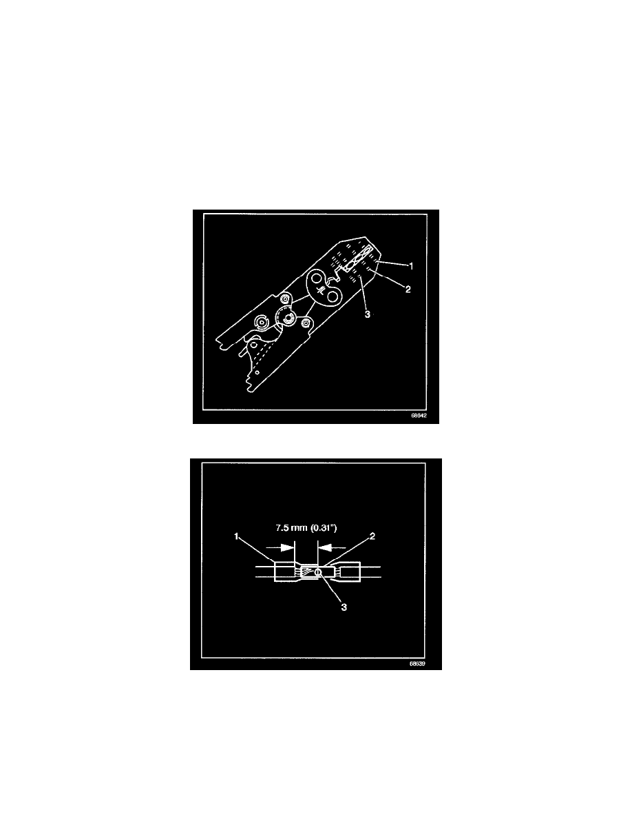
6. Place the splice sleeve in the nest. Ensure that the crimp falls midway between the end of the barrel and the stop. The sleeve has a stop (3) in the
middle of the barrel (2) in order to prevent the wire (1) from going further. Close the hand crimper handles slightly in order to firmly hold the
splice sleeve in the proper nest.