
Bravada 2WD L6-4.2L VIN S (2002)
^
Rewrap the conductors with the mylar tape.
^
Use caution not to wrap the drain wire in the tape (1).
^
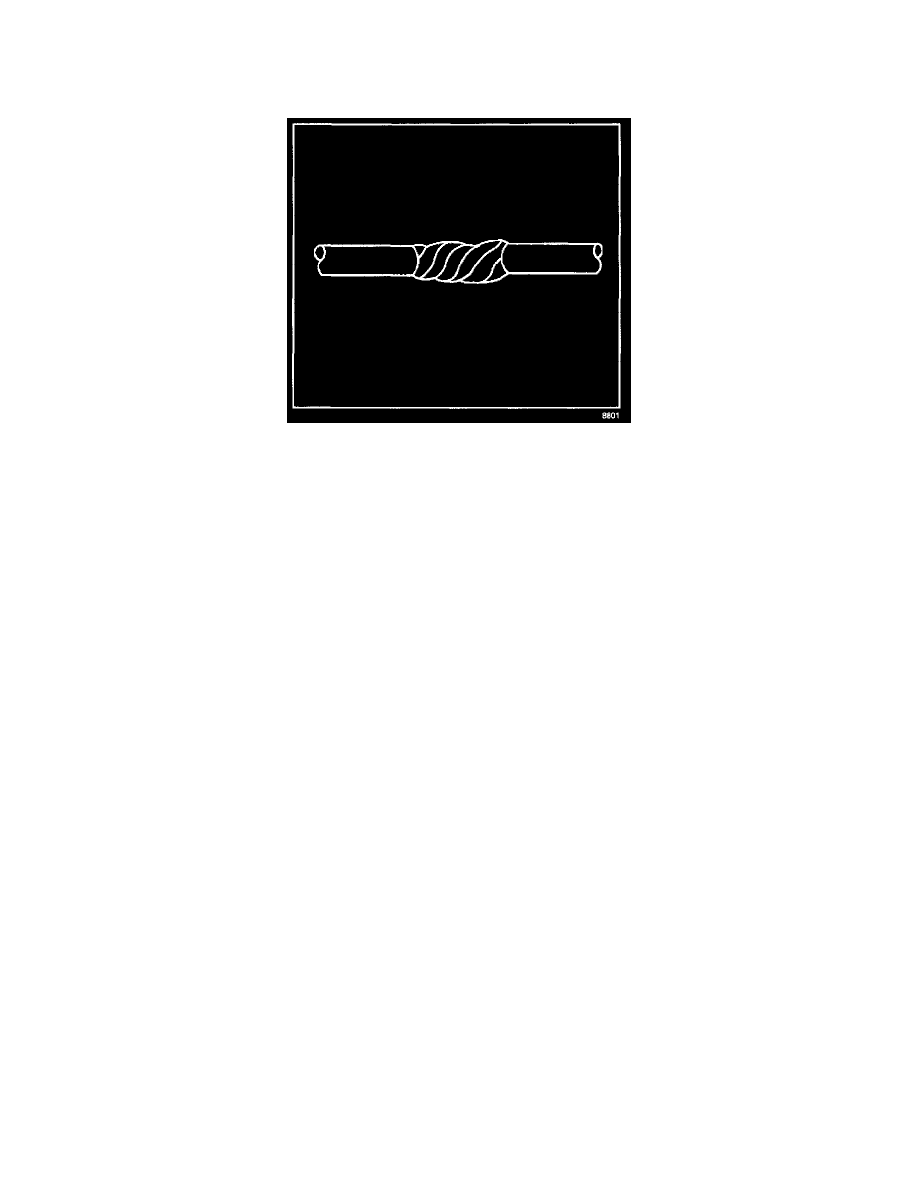
Follow the splicing instructions for copper wire and splice the drain wire.
^
Wrap the drain wire around the conductors and tape with mylar tape.
5. Tape over the entire cable. Use a winding motion when you apply the tape.
Splicing Inline Harness Diodes
Many vehicle electrical systems use a diode to isolate circuits and protect the components from voltage spikes. When installing a new diode use the
following procedure.
1. Open the harness.
^
If the harness is taped, remove the tape.
^
To avoid wiring insulation damage, use a sewing ripper in order to cut open the harness.
^
If the harness has a black plastic conduit, pull out the diode.
2. If the diode is taped to the harness, remove all of the tape.
3. Check and record the current flow direction and orientation of diode.
4. Remove the inoperative diode from the harness with a suitable soldering tool.
IMPORTANT: If the diode is located next to a connector terminal remove the terminal(s) from the connector to prevent damage from the soldering
tool.
5. Carefully strip away a section of insulation next to the old soldered portion of the wire(s). Do not remove any more than is needed to attach the
new diode.
6. Check current flow direction of the new diode, being sure to install the diode with correct bias. Reference the appropriate wiring schematic to
obtain the correct diode installation position.
7. Attach the new diode to the wire(s) using 60/40 rosin core solder. Before soldering attach some heat sinks (aluminum alligator clips) across the
diode wire ends to protect the diode from excessive heat. Follow the manufacturer's instruction for the soldering equipment.
8. Reinstall terminal(s) into the connector body if previously removed.
IMPORTANT: To prevent shorts to ground and water intrusion, completely cover all exposed wire and diode attachment points with tape.
9. Tape the diode to the harness or connector using electrical tape.
Heated Oxygen Sensor (HO2S) Wiring Repairs
TOOLS REQUIRED
J 38125-B Terminal Repair Kit
NOTE: Do not solder repairs under any circumstances as this could result in the air reference being obstructed.
If the heated oxygen sensor pigtail wiring, connector, or terminal is damaged the entire oxygen sensor assembly must be replaced. Do not attempt to
repair the wiring, connector, or terminals. In order for the sensor to function properly it must have a clean air reference. This clean air reference is
obtained by way of the oxygen sensor signal and heater wires. Any attempt to repair the wires, connectors or terminals could result in the obstruction of
the air reference and degrade oxygen sensor performance.
The following guidelines should be used when servicing the heated oxygen sensor:
^
Do not apply contact cleaner or other materials to the sensor or vehicle harness connectors. These materials may get into the sensor, causing poor
performance. Also, the sensor pigtail and harness wires must not be damaged in such a way that the wires inside are exposed. This could provide a