
Bravada 4WD V8-5.3L VIN P (2004)
22. Install the right side differential bearing adjuster into the right side differential carrier case half using the J 45224.
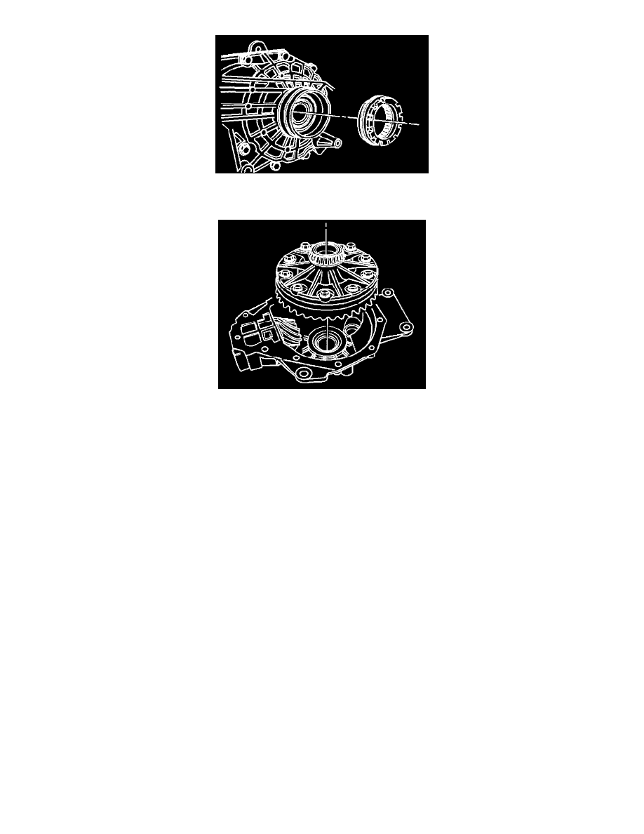
23. Install the right differential case side bearing cup into the right differential carrier case half using the J 23423-A and the J 8092.
24. Install the differential case assembly into the left differential carrier case half.
25. Install the right differential carrier case half to the left differential carrier case half.
Do not use sealer at this time.
If the carrier case halves do not make complete contact, back out the right side differential adjuster using the J 45224.
26. Install the differential carrier case bolts.
^
Tighten the differential carrier case bolts to 48 Nm (35 ft. lbs.).
27. Using the J 45224, turn the left differential adjuster nut clockwise until the differential adjuster nut contacts the differential side bearing and can no
longer be turned.
28. Using the J 45224, turn the right differential adjuster nut sleeve clockwise until the differential adjuster nut contacts the differential side bearing
and can no longer be turned.
29. Rotate the pinion several times in order to seat the bearings.
30. Measure the rotating torque of the pinion and differential assembly using an inch-pound torque wrench.
^
The rotating torque of the pinion and differential assembly should be 2.8 - 5.1 Nm (25 - 45 inch lbs.) for used bearings, or 3.4 - 6.2 Nm (30 -
55 inch lbs.) for new bearings.
31. If the rotating torque measurement is below 2.8 Nm (25 inch lbs.) for used bearings, or 3.4 Nm (30 inch lbs.) for new bearings, tighten the
differential adjuster nuts in one notch at a time on each side until the rotating torque of the pinion and differential assembly is within
specifications.
32. If the rotating torque measurement is above 5.1 Nm (45 inch lbs.) for used bearings, or 6.2 Nm (55 inch lbs.) for new bearings, loosen the
differential adjuster nuts in one notch at a time on each side until the rotating torque of the pinion and differential assembly is within
specifications.
33. Once the specified torque is obtained, rotate the pinion several times to ensure the bearings have seated.
Recheck the rotating torque and adjust if necessary.
34. Measure the drive pinion to ring gear backlash.