
Calais L4-151 2.5L VIN U TBI (1989)
Test Description:
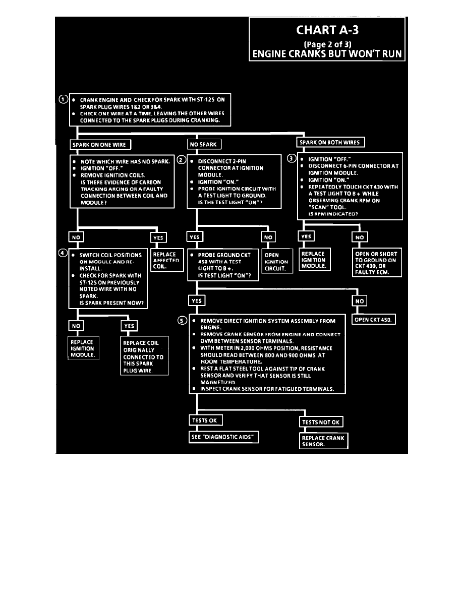
Numbers below refer to circled numbers on the diagnostic chart.
1.
The direct ignition system uses two plugs and wires to complete the circuit of each coil. The other spark plug wire in the circuit must be left
connected to create a spark.
2.
This test will determine if the 12 volt supply and a good ground is available at the DIS ignition module, 3. This test will determine if the ignition
module is not generating the reference pulse, or if the wiring or ECM are at fault. By touching and removing a test light to 12 volts on CKT 430, a
reference pulse should be generated. If rpm is indicated, the ECM and wiring are OK.
4.
This test will determine if the ignition module is not triggering the problem coil, or if the tested coil is at fault. This test could also be performed
by
substituting a known good coil. The secondary coil winding can be checked with a DVM. There should be 5,000 to 10,000 ohms across the coil towers.
There should not be any continuity from either coil tower to ground.
5.
Checks for continuity of the crank sensor and connections as well as sensor magnetism. These checks must be performed with the crank sensor at
room temperature in order to obtain accurate readings.