
Calais FWD L4-151 2.5L (1985)
Brake Master Cylinder: Description and Operation
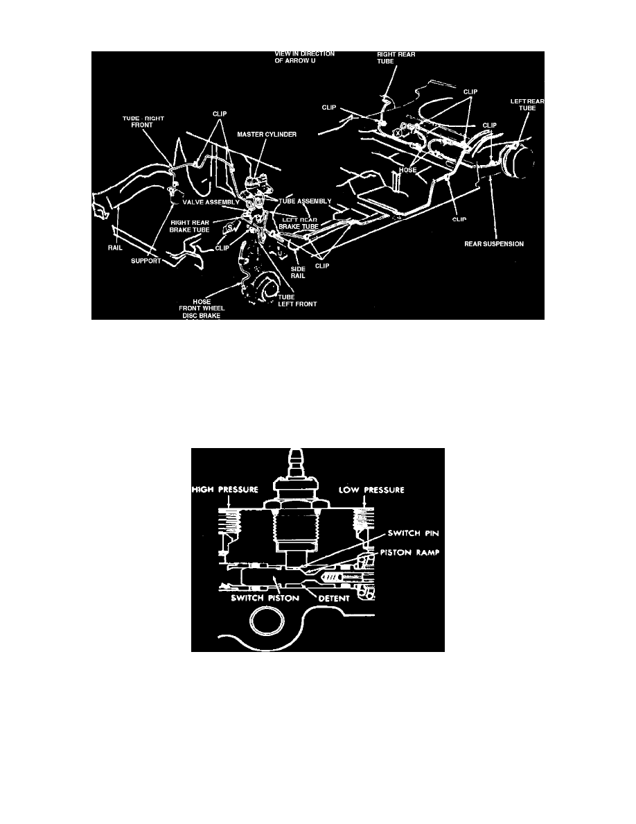
Schematic diagram of a typical hydraulic diagonally split brake system
This system operates on the same principles as conventional front and rear split systems using primary and secondary master cylinders moving
simultaneously to exert hydraulic pressure on their respective systems.
The hydraulic brake lines on this system, however, have been diagonally split front to rear (left front to right rear and right front to left rear) in
place of separate lines to the front and rear wheels. In the event of a system failure this would cause the remaining good system to do all the
braking on one front wheel and the opposite rear wheel, thus maintaining 50% of the total braking force. The hydraulic pressure loss would result
in a pressure differential in the system and cause a warning lamp on the dashboard to glow as in front and rear split systems.
Failure warning switch, rear system failure
Failure Warning Switch
If the rear brake system fails, the front system pressure forces the switch piston to the right. The switch pin is then forced up into the switch,
completing the electrical circuit and activates the dash warning lamp.
When repairs are made and pressure returns to the system, the piston moves to the left, resetting the switch. The detent on the piston requires
approximately 100 to 450 psi to permit full reset of the piston. In event of front brake system failure, the piston moves to the left and the same
sequence of events is followed as for rear system failure except the piston resets to the right.