
Ciera V6-231 3.8L (1986)
B.
Care should be taken to avoid routing feedline with any vehicle wiring.
4.
Antenna Tuning
A.
It is important that the antenna be tuned properly and reflected power be kept to a minimum. (VSWR < 2:1)
5.
Radio Wiring and Connection Locations
A.
Transceiver Power Leads:
These connections should be made directly to the battery itself, including the ground, or to the jump start block on vehicles so equipped The
transceiver power feeds should be #10 AWG wire or larger, twisted if possible The ground wire should not be attached to the body at any point.
Appropriate in-line fuses for both the positive and ground leads should be located as near the battery as possible. NOTE:
It is recommended that a fuse be placed in the transceiver ground lead to prevent possible damage to the transceiver, in the event the battery to
engine-block ground is inadvertently disconnected. For ONE-PIECE TRANSCEIVERS where ignition switch control is desired, a 12 v power
contactor must be installed in the transceiver positive lead. The contactor should be located at the vehicle battery with the coil of the contactor
driven through an appropriate in-line fuse from an available accessory circuit or ignition circuit not powered during cranking. The coil of the
contactor must return to battery negative.
B.
Handset or Control Unit Battery and Ground:
Any ground lead from a handset or control unit must return to battery negative. It is preferable that the positive lead for a handset or control unit be
connected directly to the battery. It is recommended that the handset or control unit positive and ground leads be appropriately fused separately
from the transceiver positive and ground leads. If ignition switch control is desired, the handset or control unit positive lead may be connected
through an appropriate in-line fuse to an available accessory circuit or ignition circuit not powered during cranking.
C.
Connections for Multiple Transceivers and Receivers:
If multiple transceivers or receivers are to be installed in the vehicle, power leads to the trunk or under dash should be terminated in covered
insulated buss bars. All transceivers or receivers may then have their power leads connected to the buss bars. This makes a neater installation and
reduces the number of wires funning to vehicle underhood.
6.
Wire Routing
A.
The power leads should be brought through a grommet on the driver's side firewall. For trunk-mounted transceivers, the cables should continue on
along the driver's side door sills, under the rear seat, and into the trunk through the rear bulkhead. If the battery is located on the passenger side,
battery leads should cross the vehicle in front of the engine. All attempts should be made to maintain as much distance as possible between radio
power leads and vehicle electronic modules and wiring.
B.
For police vehicles, radio power leads should be routed in the conduit provided with the option package.
7.
Troubleshooting
A.
Should vehicle problems develop following installation, the source of the problem should be determined prior to further operation of the vehicle.
B.
Possible causes of vehicle problems include:
1.
Power feeds connected to points other than the battery.
2.
Antenna location.
3.
Transceiver wiring located too close to vehicle electronic modules or wiring.
4.
Poor shielding or poor connectors on antenna feedline.
8.
Contact and Feedback
A.
GM vehicles have been designed and extensively tested for immunity to known sources of RF energy. However, it is impossible to test for every
combination of RF sources and installations. If a persistent condition is encountered, contact Delco Electronics Division on:
Dial Delco
Indiana
1-800-428-0501
1-800-382-0531
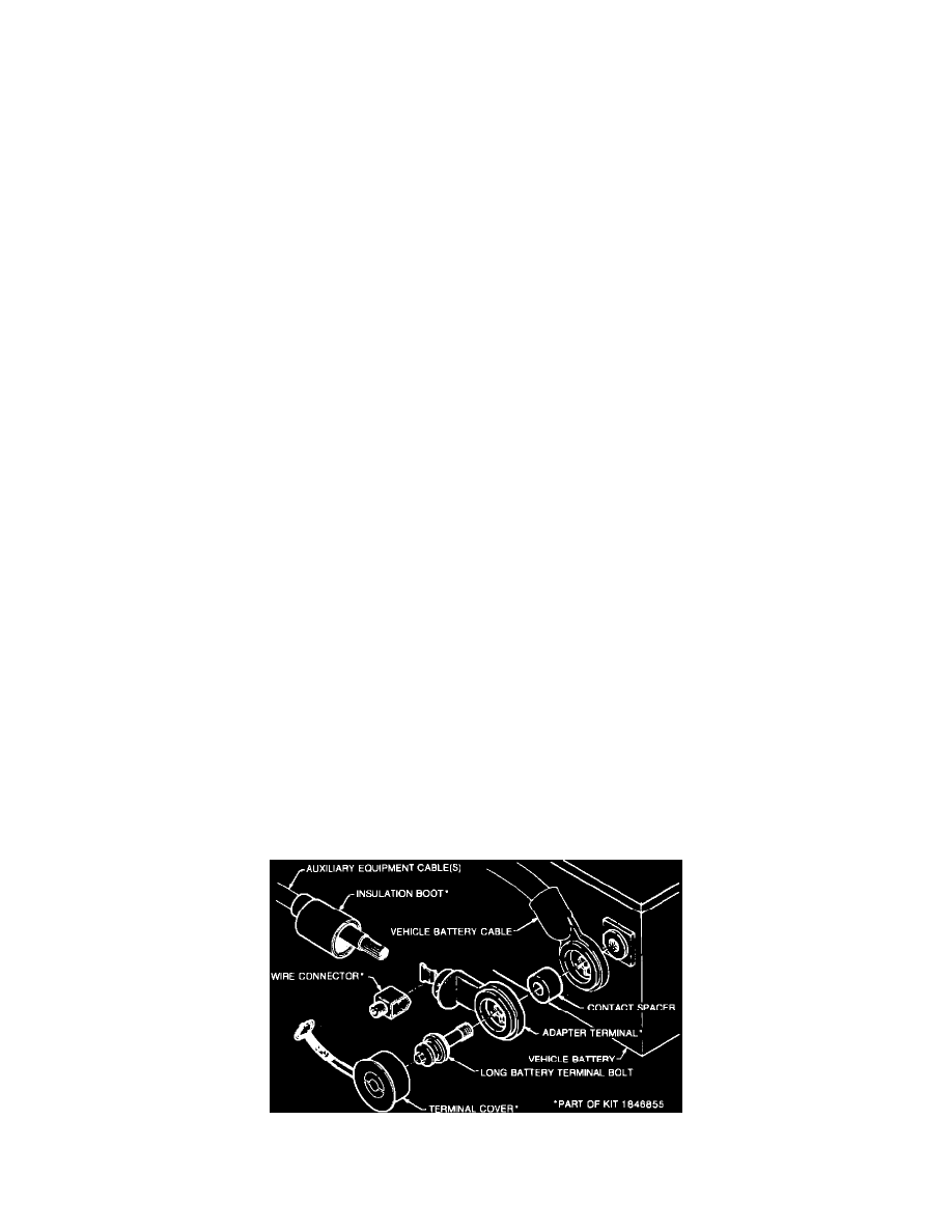
Auxiliary Electrical Equipment GM Recommended Installation
AC-Delco Side Terminal Adaptor Package 1846855, when combined with the longer battery bolt and spacer will provide the simple, tight, corrosion