
Ciera Cruiser V6-173 2.8L VIN W FI (1986)
Wiring Diagram for Chart C-12A - Coolant Fan Control Circuit
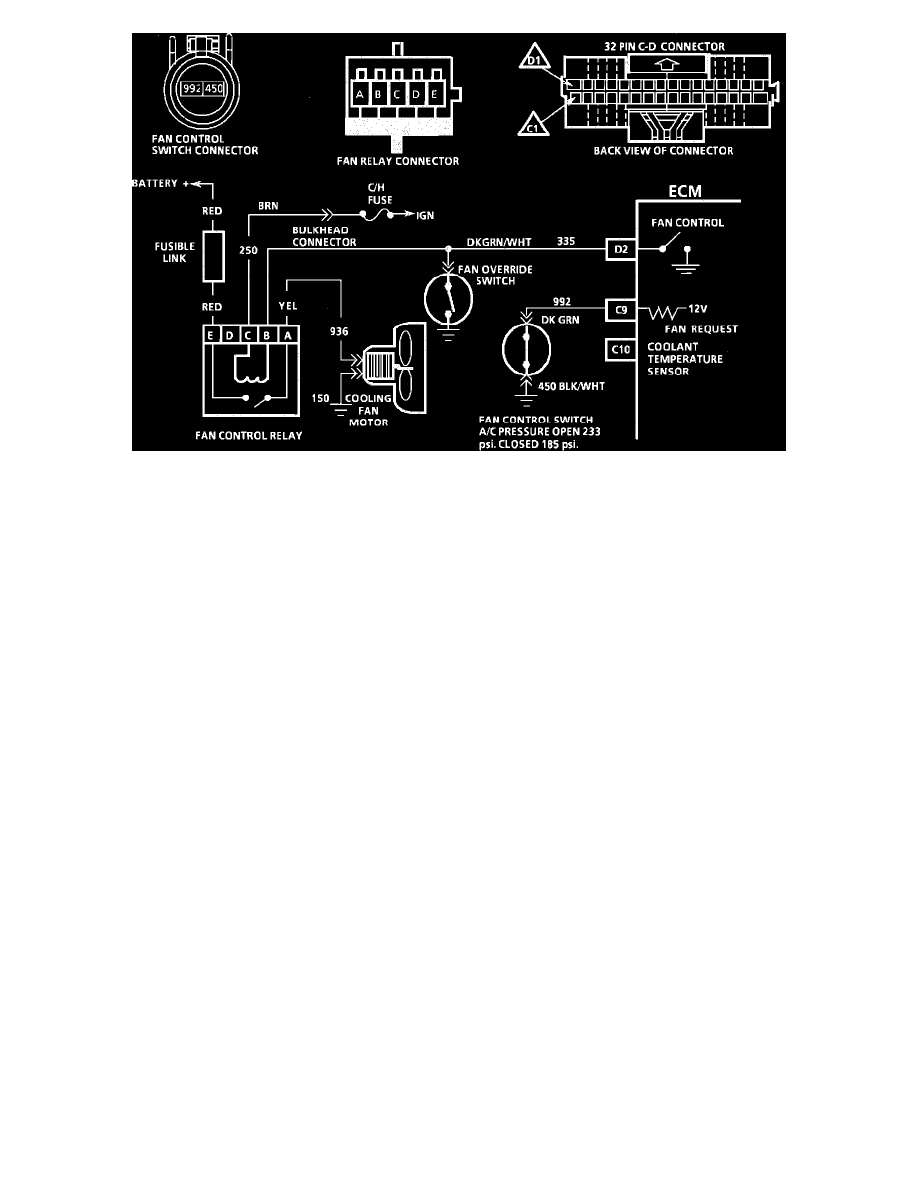
CHART C-12A - COOLANT FAN CONTROL CIRCUIT (PART 1 OF 3)
Circuit Description:
^
The cooling fan is controlled by the ECM based on inputs from the coolant sensor and fan switch. The fan should run if coolant temperature is
greater than 112~C (234~F).
^
Battery voltage is supplied to the fan relay on terminal "E" and ignition voltage to terminal "C".
^
Grounding CKT 335 (relay terminal "B") will energize the relay and supply battery voltage to the fan motor.
^
The ECM will remove the ground to CKT 335 if vehicle speed is over 40 mph.
^
The Fan override switch will also ground CKT 335 if the ECM fails to turn it "ON."
^
When A/C is used, the fan control switch mounted in the compressor will open when head pressure exceeds 1600 kPa (233 psi) and this input
causes the ECM to ground CKT 335.
^
If a Code 14 or 15 sets, the ECM will turn "ON" the cooling fan.
Note:
On 6000 STE series, CKT 335 will be grounded by the A/C control head when in the A/C mode.