
Cutlass L4-138 2.3L VIN A FI HP (1990)
proceed as follows:
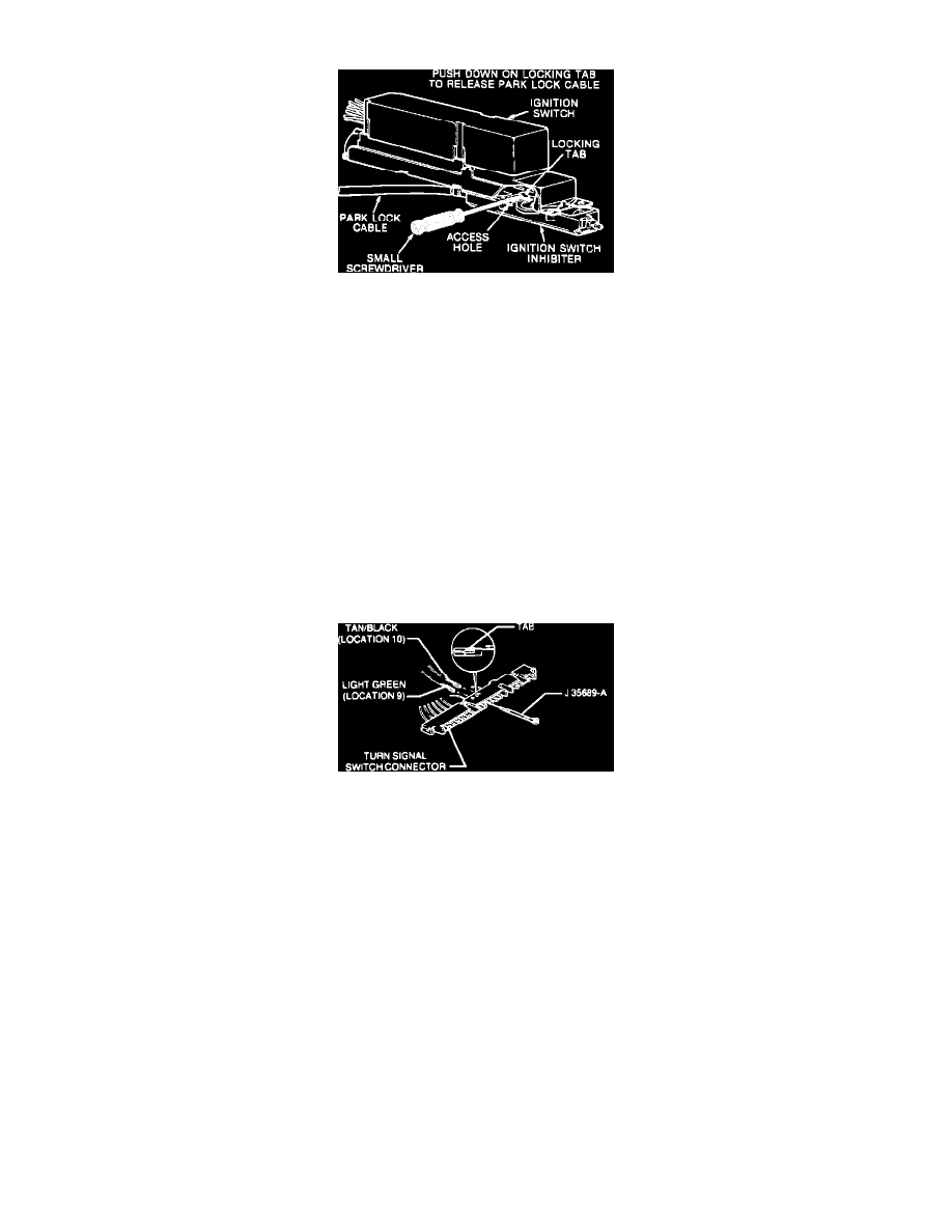
Fig. 88 Disconnecting Park Lock Cable. 1989-91 Cutlass Supreme, Grand Prix, Regal & 1990-91 Lumina W/floor Shift & Automatic Transmission
1.
Lower steering column to floor of vehicle.
2.
Remove shield or other upper column housing.
3.
Turn column lock cylinder to the On position.
4.
Disconnect park lock cable from ignition switch inhibitor with small screwdriver or punch, Fig. 88.
TURN SIGNAL CANCEL CAM ASSEMBLY, PIVOT & PULSE SWITCH ASSEMBLY & TURN SIGNAL SWITCH ASSEMBLY
Disassembly
1.
Remove nut retainer, jam nut and steering wheel.
2.
Remove turn signal cancel cam assembly, hazard knob screw and hazard warning knob.
3.
Position turn signal switch so that signal switch screws and housing cover screw can be removed through openings in switch.
4.
Remove housing cover screw and column housing cover.
5.
Disconnect wiring protector from opening in instrument panel bracket on jacket and bowl assembly and separate from wires.
6.
Disconnect pivot and pulse switch connector from ignition and dimmer switch.
7.
Remove pivot switch screw and pivot and pulse switch assembly.
8.
Remove turn signal switch screws and disconnect turn signal switch connector from ignition and dimmer switch assembly connector.
Fig. 62 Disconnecting Switch Wires
9.
Remove seventeen-way lock from turn signal connector and disconnect wires on alarm or buzzer assembly from turn signal connector with special
tool No. J 35689-A or equivalent, Fig. 62. Wrap wire ends with tape to protect during removal and installation.
10.
Remove turn signal switch assembly from column.
Assembly
1.
Install turn signal switch assembly and torque screws to 35 inch lbs.
2.
Connect wires from alarm or buzzer assembly to turn signal switch connector.
3.
Install seventeen-way secondary lock to turn signal connector and snap in place.
4.
Connect turn signal switch connector to ignition and dimmer switch connector and snap in place.
5.
Install pivot and pulse switch assembly and torque screw to 18 inch lbs.
6.
Connect pivot switch connector to ignition and dimmer switch connector and snap in place.
7.
Install wiring protector as follows:
a. Wrap protector around all wires passing through instrument panel bracket opening.
b. Close protector so that interlocking grooves engage and slide protector into instrument panel bracket opening on jacket and bowl assembly and
snap in place.
8.
Install column housing cover and torque screw to 35 inch lbs.
9.
Install hazard warning knob and torque screw to 9 inch lbs.
10.
Lubricate bottom side of cancel cam with lithium grease and install turn signal cancel cam assembly.
11.
Install steering wheel and jam nut, torque jam nut to 30 inch lbs. and secure with nut retainer.
TILT LEVER & BRACKET ASSEMBLY, WHEEL TILT SPRING, LOWER BEARING ASSEMBLY, STEERING SHAFT & HOUSING