
Cutlass V6-191 3.1L VIN M SFI (1998)
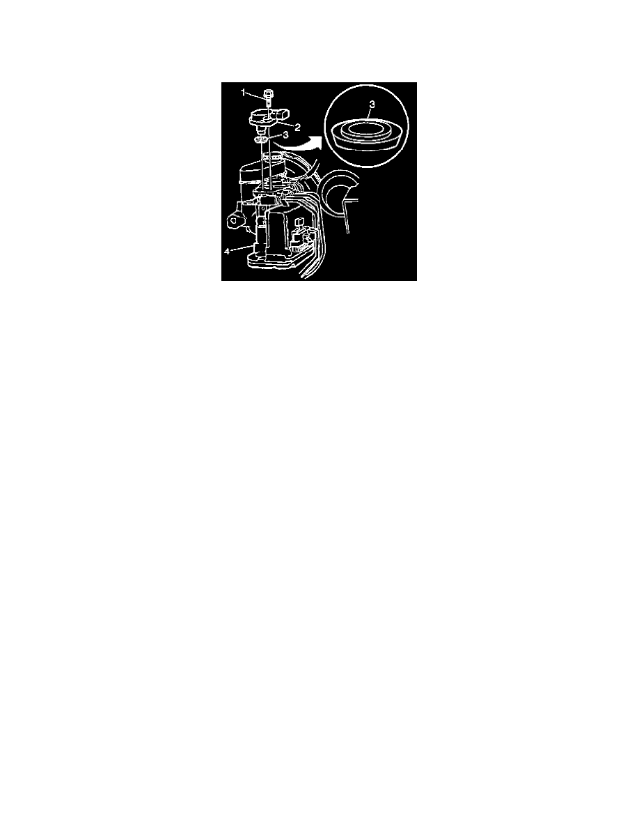
IMPORTANT: Do not attempt to disassemble the brake solenoid valve (2). The brake solenoid valve is serviceable only as an assembly.
5. Remove the brake solenoid valve (2).
INSTALLATION PROCEDURE
NOTICE: The use of rubber hoses or parts other than those specified for the Antilock Brake System (ABS) may lead to functional problems
requiring replacement of the hydraulic parts. Replace all components included in repair kits used to service this system. Lubricate rubber parts
with clean, fresh brake fluid to ease assembly. Do not use lubricated shop air on brake parts as damage to rubber components may result. If any
hydraulic component is removed or brake line disconnected, it is necessary to bleed the entire brake system. The fastener tightening specifications
are for dry, unlubricated fasteners.
1. Use the following procedure in order to install the brake solenoid valve lip seal (3):
1.1. Lubricate the seal (3) on the new brake solenoid valve (2) with clean brake fluid.
1.2. Verify that the brake solenoid valve lip seal (3) is properly positioned before installing the brake solenoid valve (2) in the ABS brake
modulator (4).
2. Position the brake solenoid valve (2) so that the brake solenoid valve electrical connector will face the same direction as the brake solenoid valve
that was removed.
3. By hand, press down firmly on the brake solenoid valve (2) until the brake solenoid valve flange seats on the ABS brake modulator (4).
4. Install the Torx head bolts (1).
-
Tighten the Torx head bolts (1) to 4.5 Nm (40 in. lbs.).
NOTICE: Refer to Fastener Notice in Service Precautions.
IMPORTANT: Verify proper installation of the brake solenoid valve connectors on the correct brake solenoid valve (2).
5. Install the brake solenoid valve electrical connector onto the brake solenoid valve (2).
6. Install the battery tray.
7. Install the Battery.
8. Bleed the brake modulator/master cylinder assembly.
9. Perform the Diagnostic System Check.
Modulator Gear Cover Replacement
REMOVAL PROCEDURE
1. Remove the Brake Modulator Assembly.
2. Remove the Torx head screws that attach the gear cover.
3. Remove the gear cover.
INSTALLATION PROCEDURE
1. Install the gear cover onto the modulator assembly.
2. Install the Torx head screws.
-
Tighten the Torx screws to 4 Nm (36 in. lbs.).
NOTICE: Refer to Fastener Notice in Service Precautions.