
Cutlass V6-262 43L DSL VIN V FI (1983) Hydraulic Brake Booster Service & Repair
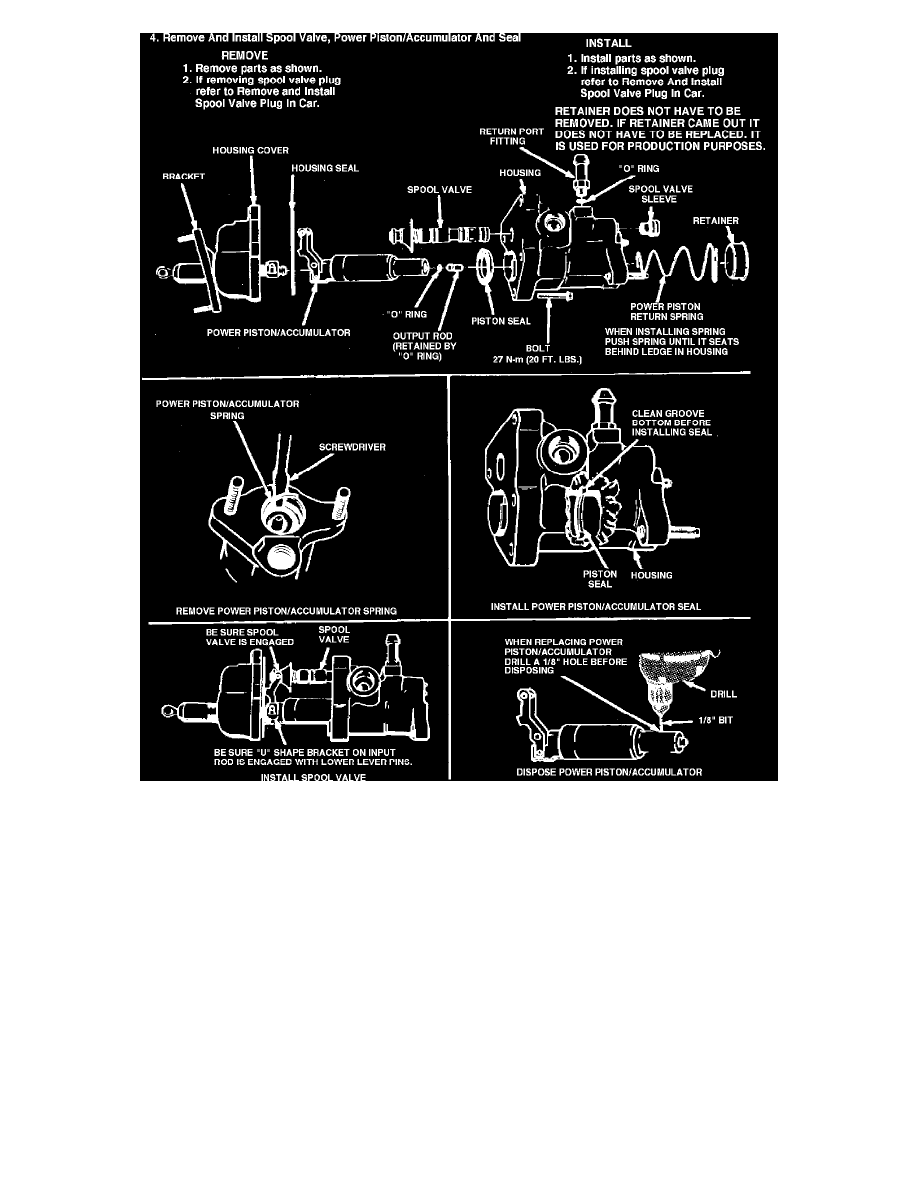
Fig. 4 Hydro-boost unit disassembly (part 2 of 2). HB-II
Refer to Fig. 4 for disassembly and assembly of Hydro-boost II unit.
Cleaning & Inspection
Keep all disassembled parts clean until assembly. Lubricate all seals and metal friction points with power steering fluid. When unit is disassembled, all
seals and tube inserts should be replaced. These parts are available in replacement kits. If any accumulator valve components are damaged or lost,
replace all valve components.
1.
Inspect spool valve and spool valve bore for corrosion, nicks, scoring or other damage. Discoloration of the spool or bore, particularly in the
groove areas, is not harmful and replacement is not necessary.
2.
If spool valve or bore has nicks or scoring that can be felt with a fingernail, the entire booster should be replaced as an assembly. The clearance
between the spool valve and the spool valve bore is important. Because of this, the spool valve and the housing make up a selective
assembly. The spool valve is selected to match the spool valve bore.
3.
Inspect piston for scratches and nicks. If scratches on the outside surface can be felt with a fingernail, replace piston.
Description
Hydro-boost II is a hydraulically operated power brake booster. The hydraulic brake booster consists of an open center spool valve and a hydraulic
cylinder combined into a single housing. The power steering pump provides the hydraulic fluid pressure to operate both the power brake booster and the