
Cutlass Ciera V6-3100 3.1L VIN M SFI (1996)
Engine Control Module: Service and Repair
PCM Service
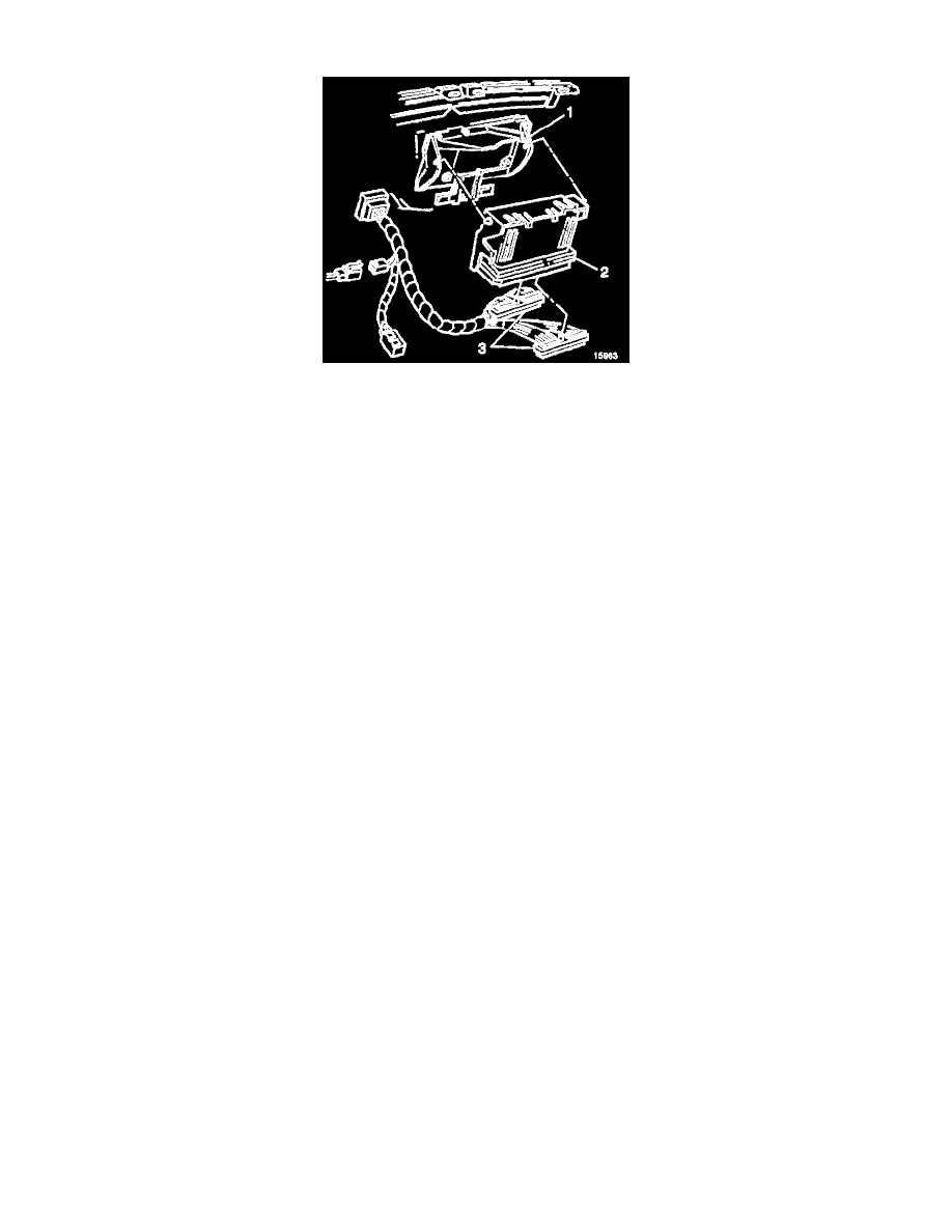
IMAGE LEGEND
(1) PCM BRACKET
(2) PCM
(3) PCM TERMINAL CONNECTORS
Service of the PCM should normally consist of either replacement of the PCM or EEPROM programming. If the diagnostic procedures call for the PCM
to be replaced, PCM should be checked first to see if it is the correct part. If it is, remove the faulty PCM and install the new service PCM.
CAUTION:
-
In order to prevent possible Electrostatic Discharge damage to the PCM, Do Not touch the connector pins or the soldered components on the
circuit board.
-
In order to prevent internal PCM damage, leave the ignition OFF when installing or removing the PCM connectors and disconnecting or
reconnecting the power to the PCM (battery cable, PCM pigtail, PCM fuse, jumper cables, etc.).
-
When replacing the production PCM with a service PCM, it is important to transfer the broadcast code and production PCM number to the service
PCM label. Do not record on PCM cover. This will allow positive identification of PCM parts throughout the service life of the vehicle.
THE SERVICE PCM EEPROM WILL NOT BE PROGRAMMED. DTC PO6O2 indicates the EEPROM is not programmed or has malfunctioned.
REMOVAL PROCEDURE
1. Disconnect the negative battery cable.
2. Remove the right hand sound insulator.
3. Remove the PCM.
4. Remove the PCM connectors.
5. Remove the PCM access cover.
6. Remove the Knock Sensor (KS) module.
INSTALLATION PROCEDURE
1. If a new PCM is being installed, install the KS module from the original PCM. Refer to Knock Sensor (KS) System.
2. Install the access cover on PCM.
3. Install the connectors to PCM.
4. Install the PCM.
5. Install the right hand sound insulator.
6. Connect the negative battery cable. If a new PCM is being installed, program the EEPROM.
If a new PCM is being installed, program the EEPROM.
EEPROM PROGRAMMING
1. Set-up - Ensure that the following conditions have been met:
^
The ignition is ON.
^
The Vehicle Interface Module (VIM) cable connection at the Data Link Connector (DLC) is secure.