
Cutlass Ciera Cruiser V6-3300 3.3L MFI VIN N (1993)
TCC Circuit
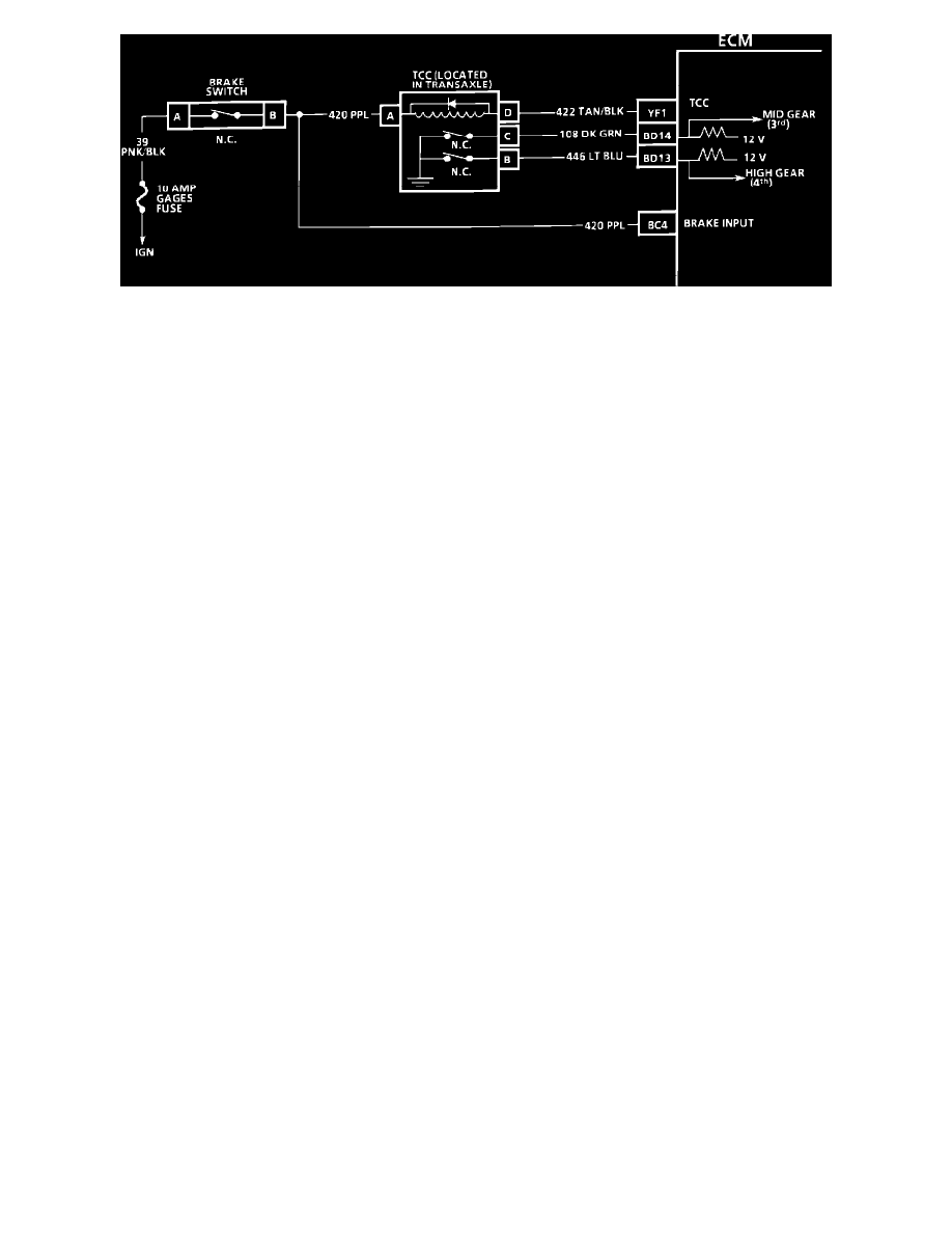
CIRCUIT DESCRIPTION:
Each gear switch opens when the appropriate clutch is applied. All gear switches are open in fourth gear.
TEST DESCRIPTION: Numbers below refer to circled numbers on the diagnostic chart.
1.
Some "Scan" tools display the state of these switches in different ways. Be familiar with the type of tool being used. Since both switches should be
in the closed state during this test, the tool should read the same for either the 3rd or 4th gear switches.
2.
Determines whether the switch or signal circuit is open. The circuit can be checked for an open by measuring the voltage (with a voltmeter) at the
TCC connector. Should be about 12 volts.
3.
Because the switch(s) should be grounded in this step, disconnecting the TCC connector should cause the "Scan" switch state to change.
4.
This switch state should change when the vehicle shifts into 3rd gear.
DIAGNOSTIC AIDS:
If vehicle is road tested because of a TCC related problem, be sure the switch states do not change while in 4th gear, because the TCC will
disengage. If switches change state, carefully check wire routing and connections. If the ECM, TCC solenoid, and control circuitry are functioning
correctly and the TCC still does not apply properly, the problem may be hydraulic or mechanical.