
Cutlass Supreme V6-204 3.4L DOHC VIN X SFI (1995)
Antenna: Initial Inspection and Diagnostic Overview
Circuit Operation
When the Radio is turned "ON," voltage from CKT 43 is applied from the Radio and CKT 145 to the internal Antenna Relay coil. The relay contacts
close and battery voltage is supplied to the Antenna Motor. The Antenna Motor is grounded through the Up Switch and the relay contacts. The Motor
drives the Antenna up. When the Antenna is at its full height, the Up Switch opens and the Motor stops.
When the Radio or Ignition Switch is turned "OFF," the circuit through the internal Antenna Relay coil is opened. The Antenna Relay contacts open to
the position shown in the schematic, applying battery voltage to the Down Switch. The opposite side of the motor is now grounded. Since the Down
Switch at the Antenna is now making contact to the Battery voltage, the voltage to the Motor has reversed polarity. It runs in the opposite direction and
drives the Antenna down.
At the end of the Antenna's travel, the Down Switch opens and breaks the current flow. Both sets of switches are now in the positions shown in the
schematic, the Radio is "OFF," and the Antenna is down.
The Antenna is connected to the Radio by coaxial cable.
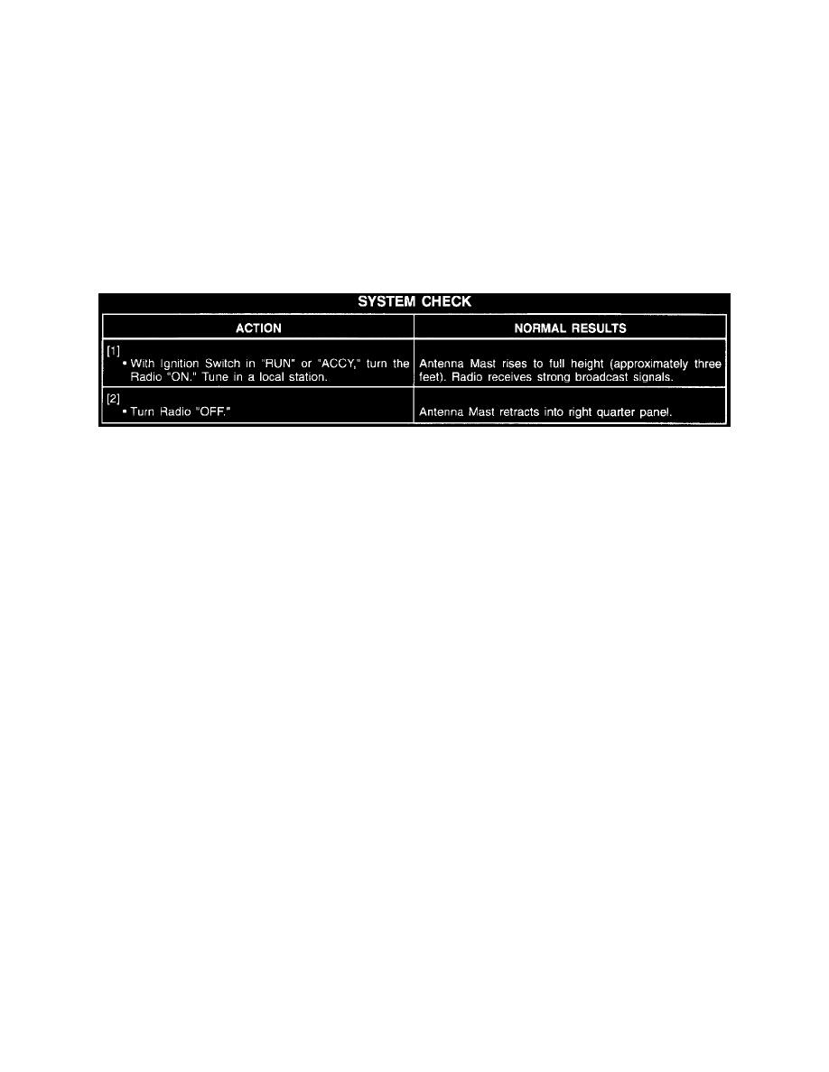
System Check
System Diagnosis
Perform the System Check and refer to the Symptom Table for the proper diagnostic procedure(s).
See: System Check
See: Symptom Related Diagnostic Procedures/Symptom Table
Troubleshooting Hints
1. Check fuse 19.
2. Check fuse 38.
3. If Power Antenna goes up or down only part way, check Power Antenna Mast for bent or dirty condition.
4. If Power Antenna goes up and down properly, but the Radio does not receive, refer to Radio/Stereo for diagnosis. See: Radio, Stereo, and
Compact Disc
^
Check for a broken (or partially broken) wire inside of the insulation which could cause system malfunction but prove "GOOD" in a
continuity/voltage check with a system disconnected. These circuits may be intermittent or resistive when loaded, and if possible, should be
checked by monitoring for a voltage drop with the system operational (under load).
^
Check for proper installation of aftermarket electronic equipment which may affect the integrity of other systems (refer to General
Troubleshooting Procedures). See: Diagrams/Diagnostic Aids
^
Refer to System Diagnosis. See: System Diagnosis