
Cutlass Supreme V6-204 3.4L DOHC VIN X SFI (1995)
Brake Warning Indicator: Initial Inspection and Diagnostic Overview
Circuit Operation
Battery voltage is applied to the "BRAKE" Warning Indicator when the Ignition Switch is in "RUN," "BULB TEST" or "START" Four switches are
connected to the "BRAKE" Warning Indicator. When any of these switches close, ground is provided and the indicator lights.
The Ignition Switch provides a ground when it is in the "BULB TEST" and "START" positions.
The Park Brake Switch provides a ground when the Park Brake is applied.
The Brake Fluid Level Indicator Sensor closes to light the "BRAKE" Warning Indicator with low brake fluid in one of the two hydraulic brake fluid
reservoirs. This could be caused by a leak in one of the brake lines. The sensor can be reset to "OPEN" by refilling the reservoir; however, this can only
be accomplished after the system is repaired.
The Electronic Brake Control Module (EBCM) closes to light the "BRAKE" Warning Indicator and sets a diagnostic trouble code when an Antilock
Brake System (ABS) malfunction may affect base brake operation.
System Diagnosis
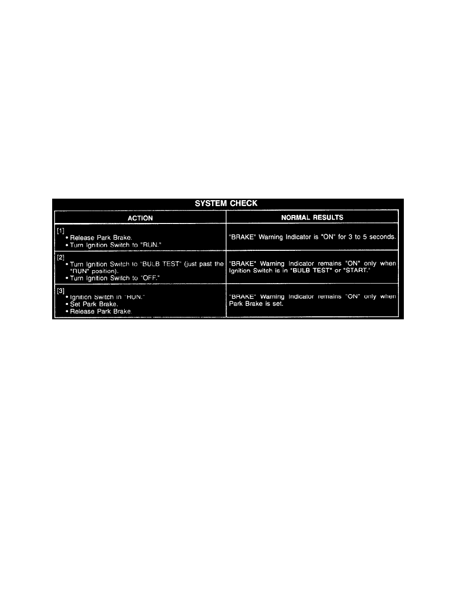
Perform the System Check and refer to the Symptom Table for the appropriate diagnostic procedures.
See: System Check
See: Symptom Related Diagnostic Procedures/Symptom Table
System Check
Troubleshooting Hints
1. Check Fuse 39.
2. Check that G119 is clean and tight.
3. Check brake fluid. If low, refer to Brakes and Traction Control. See: Brakes and Traction Control
4. If brake fluid is low and the "BRAKE" Warning Indicator does not light, check the Brake Fluid Level Indicator Sensor.
5. If equipped with Antilock Brakes and "BRAKE" Warning Indicator is lit, check for trouble codes. Refer to Brakes and Traction Control. See:
Brakes and Traction Control
^
Check for a broken (or partially broken) wire inside of the insulation which could cause system malfunction but prove "GOOD" in a
continuity/voltage check with a system disconnected. These circuits may be intermittent or resistive when loaded, and if possible, should be
checked by monitoring for a voltage drop with the system operational (under load).
^
Check for proper installation of aftermarket electronic equipment which may affect the integrity of other systems (refer to General
Troubleshooting Procedures). See: Diagrams/Diagnostic Aids
^
Refer to System Diagnosis. See: System Diagnosis