
Cutlass Supreme RWD V8-307 5.0L (1988)
Alternator: Description and Operation
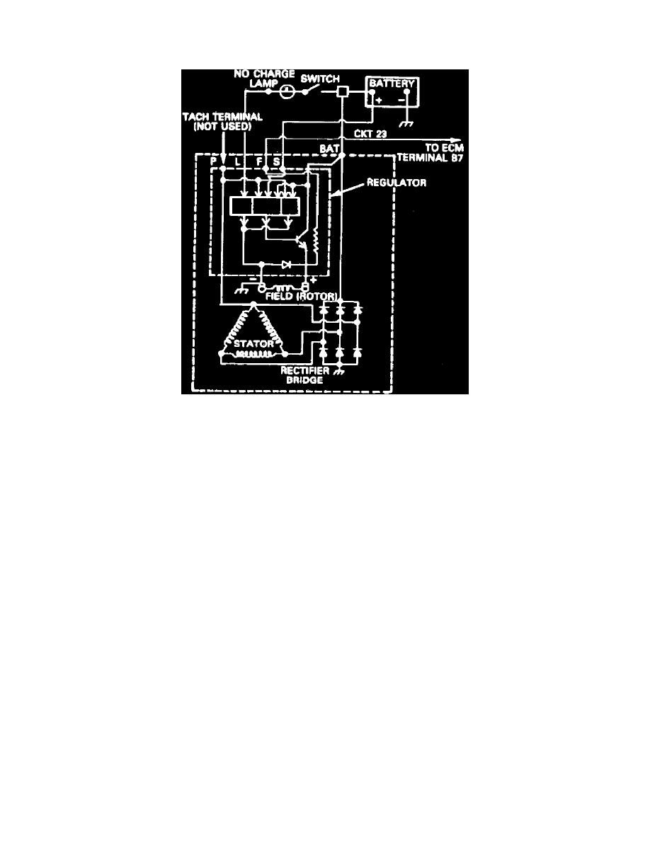
Delcotron Type CS Charging System
Fig. 1 CS charging system wiring diagram
The CS alternator is available in three sizes: CS121, CS130 and CS144. The numerals denote the outer diameter of the stator laminations and the
letters CS stand for charging system.
CS alternators use a new type regulator and a diode trio is not used. A delta stator, rectifier bridge, and rotor with slip rings and brushes are
electrically similar to earlier alternators. A conventional pulley and fan is used and, on CS-130, an internal fan cools the slip ring end frame, rectifier
bridge and regulator.
CS130 and CS144 alternators may be used with only two connections Fig. 1, battery positive and an L terminal to charge the indicator bulb. Use of P,
F and S terminals is optional. The P terminal is connected to the stator, and may be connected to a tachometer or other device. The F terminal is
connected internally to field positive, and may be used as a fault indicator. The S terminal may be connected externally to a voltage, such as battery
voltage, to sense voltage to be controlled.
The regulator voltage setting varies with temperature, and limits system voltage by controlling rotor field current.