
Delta 88 V6-3800 3.8L (1988)
Crankshaft Position Sensor: Technical Service Bulletins
Engine Controls - Temporary CKP Adjusting Procedure
NUMBER:
88-T-28
CORP. REF. NO.: 806102
DATE:
February 1988
SECTION:
6E
SUBJECT
TEMPORARY CRANKSHAFT SENSOR
ADJUSTING PROCEDURE
MODELS/YEARS
1988 DELTA 88, NINETY-EIGHT, AND
TORONADO MODELS EQUIPPED WITH 3800 ENGINES (VIN CODE C)
The 1988 3800 V-6 engine is equipped with an improved ignition system which is called a "Fast Start", due to its ability to identify which cylinders to
direct spark to within one third (120~) of a crankshaft revolution. Previous C3I systems could take as long as two crankshaft revolutions to synchronize
and initiate spark, because they had to wait for the camshaft sensor pulse.
This new ignition system features dual hall effect switches, contained in a single crankshaft position sensor assembly. Dual interrupter rings are mounted
on the rear of the crankshaft harmonic balancer. The outer ring has eighteen equally sized and equally spaced teeth while the inner ring has three spaces
(windows) which are 10, 20, and 30 degrees in width.
With this new design, exact positioning of the dual hall effect switches (crankshaft sensor assembly) between the interrupter rings is critical. A new
crankshaft sensor positioning tool, J 37089 has been developed for this purpose, which will also check the concentricity of the interrupter rings to detect
bent vanes that otherwise might go unnoticed by visual inspection. This tool will be released to all dealerships in the very near future; however, until the
time of its receipt, if it is necessary to replace the crankshaft sensor, the following procedure should be followed:
1.
With the harmonic balancer removed, install crankshaft sensor pedestal assembly to engine and torque bolts to 30 N-m (22 ft.lbs.).
2.
Loosen the pinch bolt on the new sensor pedestal until the sensor is free to slide in the pedestal.
3.
Reinstall harmonic balancer while making sure that both interrupter rings are properly aligned in the crankshaft sensor slots. Torque balancer bolt
to 297 N-m (220 ft.lbs.).
4.
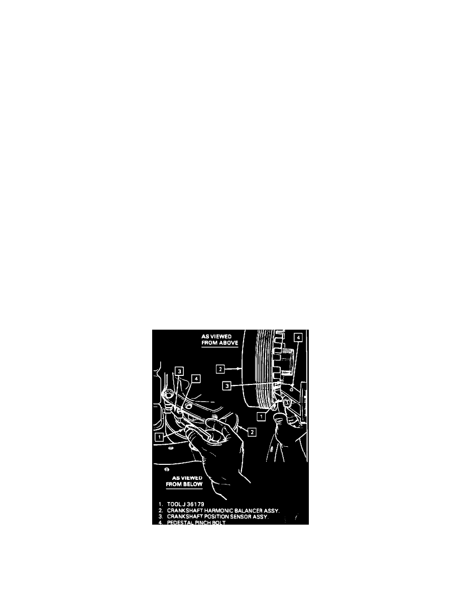
Rotate the harmonic balancer until one tooth of the outer interrupter ring fills the outer sensor slot.
FIGURE 1
5.
Insert one gage strip of the adjustment tool J 36179 between the outer interrupter ring and sensor (see Fig. 1).
6.
Torque sensor retaining pinch bolt to 4 N-m (35 in.lbs.) while maintaining light pressure on sensor against gauge and interrupter ring. This