
Eighty-Eight Royale FWD V6-3.8L SC VIN 1 (1995)
Remote Accessory Control (RAC): Initial Inspection and Diagnostic Overview
Circuit Operation
Retained Accessory Power (RAP) allows the radio, power windows and sunroof to be operated for approximately 10 minutes after turning the ignition
switch to "OFF."
When the ignition switch is turned to "ACCY" or "RUN," battery voltage is applied from RH underhood fuse block Fuse 2 through the ignition switch
and the normally closed contracts of RAP relay number 1 to power the radio. Battery voltage is also applied from I/P fuse block fuse 1D to the ignition
sense input, C1/B, of the Remote Accessory Control (RAC) module. When the ignition switch is turned to "OFF," the RAC module terminal C1/B
senses this and turns on its output at terminal C1/H. This applies battery voltage, made available from RAC module terminal C 1/A, to the coil of RAP
relay number 1, energizing the coil. With RAP relay number 1 energized, battery voltage from RH underhood fuse block 2 is applied directly through the
closed contacts of RAP relay number 1 to power the radio. The radio operates for approximately 10 minutes or until any door is opened. If any door is
opened, RAC module terminal C1/C is grounded thereby turning off the output at terminal C1/H, de-energizing RAP relay number 1, and removing
power from the radio. The 10-minute time interval can be reset by turning the ignition switch to "RUN," then back to "OFF"
Operation of RAP relay no. 2 is similar to that of RAP relay number 1, however, the RAC module terminal C1/F supplies battery voltage when the
ignition switch is turned to either "RUN" or "OFF." RAP is made available to the power windows and sunroof, by turning on RAC module output
terminal C1/F.
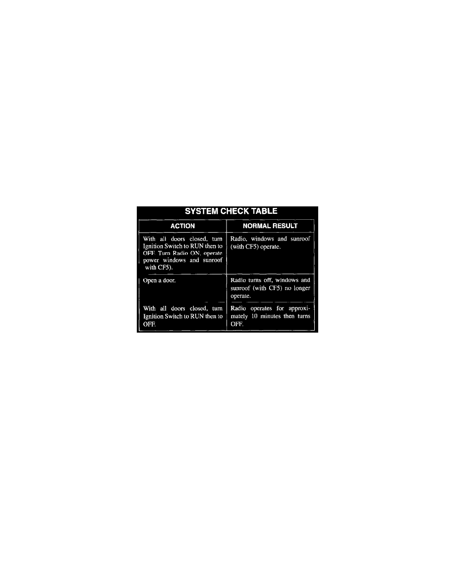
System Check
System Check Table
^
Use System Check Table as a guide to normal operation.
^
Refer to System Diagnosis for a list of symptom and diagnostic steps.
^
Refer to System Diagnosis when a result is not normal.
System Diagnosis
^
Do tests listed for your symptom in Symptom Table.
^
Refer Diagnostic Tests for Diagnostic procedure.
Troubleshooting Hints
TRY FOLLOWING BEFORE DOING SYSTEM CHECK.
1. Check Relay Center Fuse 2 by visual inspection.
2. Check I/P Fuse Block Fuse 1D by visual inspection.
3. Check RH Underhood Fuse Block Fuse 2 by visual inspection.
4. Check LH Underhood Fuse Block Fuse 7 by visual inspection.
^
Refer to System Check for a guide to normal operation.
^
Refer to System Diagnosis for diagnostic tests.