
Intrigue V6-3.8L VIN K (1998)
Weather Pack Connectors
^
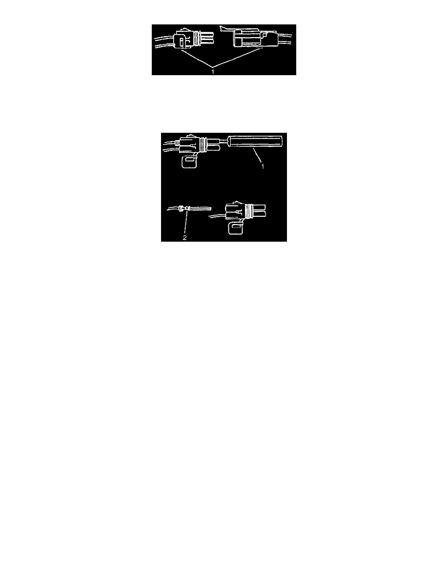
Separate the connector halves (1)
^
Open the secondary lock. A secondary lock aids in terminal retention and is usually molded to the connector (1).
^
Grasp the wire and push the terminal to the forward most position. Hold the wire in this position.
Weather Pack Connectors
^
Insert the Weather Pack(R) terminal removal tool into the front (mating end) of the connector cavity until it rests on the cavity shoulder (1).
^
Gently pull on the wire to remove the terminal through the back of the connector (2).
IMPORTANT: Never use force to remove a terminal from a connector.
^
Inspect the terminal and connector for damage. Repair as necessary. Refer to Repairing Connector Terminals.
^
Reform the lock tang (2) and reset terminal in connector body.
^
Close secondary locks and join connector halves.
^
Verify that circuit is complete and working satisfactorily.
^
Perform system check.
Basic Knowledge Required
Without a basic knowledge of electricity, it will be difficult to use the diagnostic procedures contained in this section. You should understand the basic:
theory of electricity and know the meaning of voltage (volts), current (amps) and resistance (ohms). You should understand what happens in a circuit
with an open or a shorted wire. You should be able to read and understand a wiring diagram.
The following fourstep troubleshooting procedure is recommended:
Check the Problem
Perform a System Check to determine a symptom. Don't waste time fixing part of the problem. Do not begin disassembly or testing until you have
narrowed down the possible causes.
Read the Electrical Schematic
Study the schematic and read the Circuit Description text to gain an understanding of how the circuit should work. Check circuits that share wiring
with the problem circuit. (Shared circuits are shown on Power Distribution and Ground Distribution.) Try to operate the shared circuits. If the
shared circuits work, then the shared wiring is OK. The cause must be within the wiring used only by the problem circuit. If several circuits fail at
the same time, chances are the power (fuse) or ground circuit is faulty.
Find the fault and repair
Narrow down the possible causes.
^
Check System Fuse(s).
^
Check System Ground(s)
^
For systems with bulb failures, check bulb(s) prior to beginning diagnostic tables.
^
Perform a visual inspection of system components, and accessible related wiring prior to beginning diagnostic tables.
Make the necessary measurements or checks as given in the System Diagnosis.