
Intrigue V6-3.8L VIN K (1998)
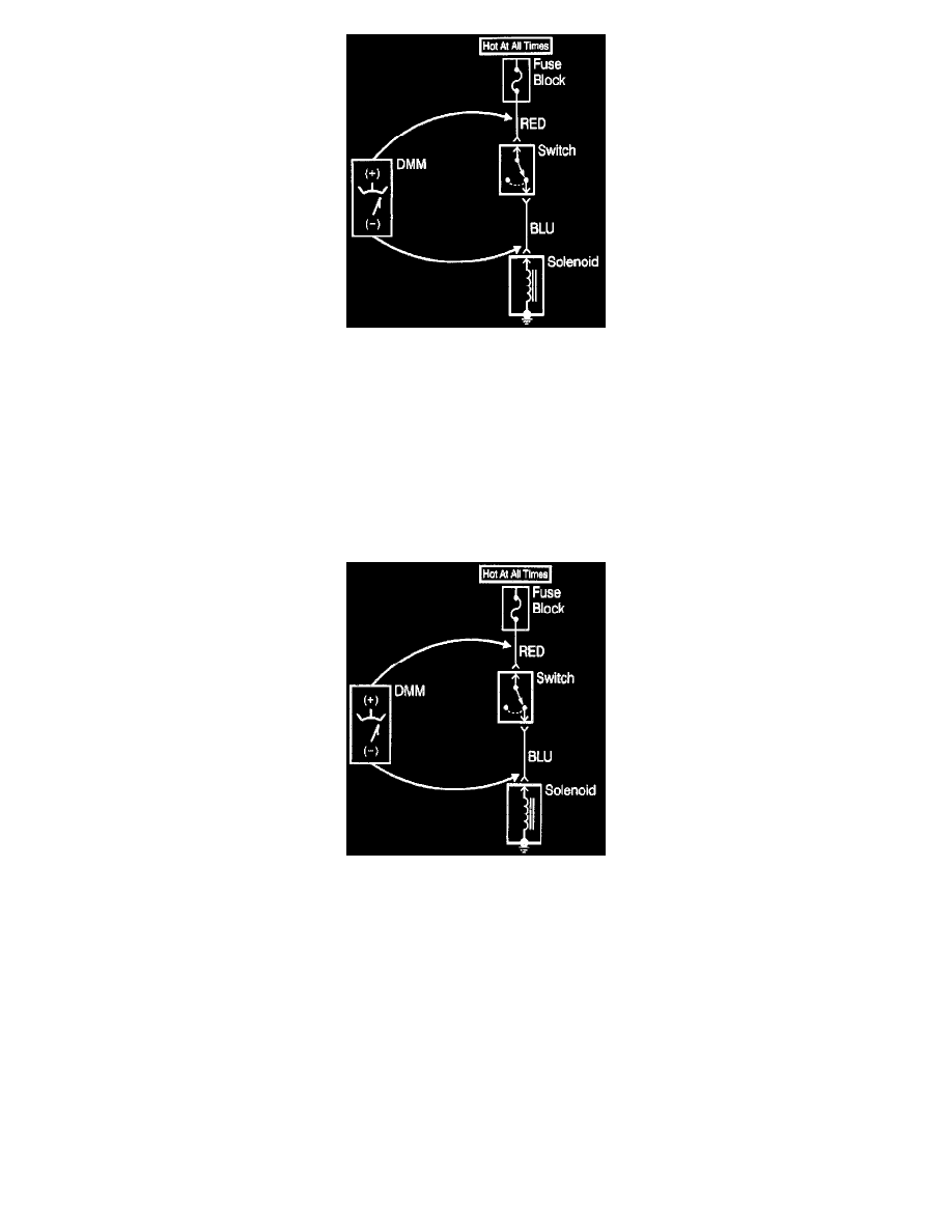
Testing For Voltage
This test checks for voltage along a wire through a connection or switch.
1. Apply power to the circuit.
2. Place meter leads in the COM (black) and V ohm inputs.
3. Place the rotary switch (meter) in the V (AC) or V (DC) position.
4. Connect the positive lead of a DMM to the end of the wire, (or to one side of the connection or switch) which is closer to the battery.
5. Connect the negative lead to the other end of the wire (or the other side of the connection or switch).
6. Operate the circuit.
Testing For Voltage Drop
Testing For Voltage Drop
This test checks for voltage being lost along a wire or through a connection or switch.
1. Connect the positive lead of a DMM to the end of the wire or to one side of the connection, or to the switch whichever is closer to the battery.
2. Connect the negative lead to the other end of the wire or to the other side of the connection, or switch.
3. Operate the circuit.
4. The DMM will show the difference in voltage between the two points.
Test Light
A test light can simply and quickly check a circuit for voltage.
The J 34142-B test light is comprised of a 12 volt light bulb with an attached pair of leads. To properly operate this tool use the following procedure.
1. Attach one lead to ground.
2. Touch the other lead to various points along the circuit where voltage should be present.
3. When the bulb illuminates, there is voltage at the point being tested.
Digital Multimeter (Dmm)
IMPORTANT: Circuits which include any solid state control modules, such as the PCM, should be tested only with a 10 megohm or higher impedance