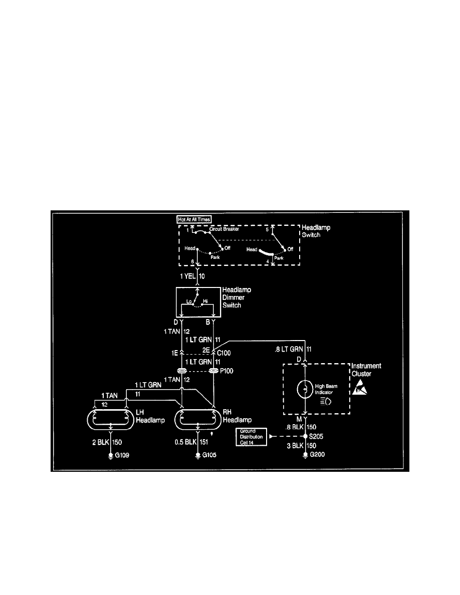
Intrigue V6-3.8L VIN K (1998)

Before replacing a component, check power, signal and ground wires at the component harness connector. If the checks and connections are OK,
the most probable cause is component failure.
Test the Repair
Repeat the System Check to verify that the fault has been corrected and that no other faults were induced during the repair.
Checking Aftermarket Accessories
IMPORTANT: Do not connect aftermarket accessories into the following circuits:
^
SIR circuits, all such circuits are indicated on circuit diagrams with the SIR symbol.
^
OBDII circuits, all such circuits are indicated on circuit diagrams with the OBDII symbol.
Always check for aftermarket accessories (non-OEM) as the first step in diagnosing electrical problems. If the vehicle is so equipped, disconnect the
system to verify that these add-on accessories are not the cause of the problems.
Possible causes of vehicle problems related to aftermarket accessories include:
^
Power feeds connected to points other than the battery.
^
Antenna location.
^
Transceiver wiring located too close to vehicle electronic modules or wiring.
^
Poor shielding or poor connectors on antenna feed line.
^
Check for recent service bulletins detailing installation guidelines for aftermarket accessories.
Intermittent and Poor Connections
Intermittent & Poor Connections Diagnosis
Most intermittents are caused by faulty electrical connections or wiring, although occasionally a sticking relay or solenoid can be a problem. Some items
to check are:
^
Poor mating of connector halves, or terminals not fully seated in the connector body (backed out).
^
Dirt or corrosion on the terminals. The terminals must be clean and tree of any foreign material which could impede proper terminal contact.
^
Damaged connector body, exposing the terminals to moisture and dirt, as well as not maintaining proper terminal orientation with the component
or mating connector.
^
Improperly formed or damaged terminals. All connector terminals in problem circuits should be checked carefully to ensure good contact tension.
Use a corresponding mating terminal to check for proper tension. Refer to Checking Terminal Contact for the specific procedure.
^
The J35618-A must be used whenever a diagnostic procedure requests checking or probing a terminal. Using the adapter will ensure that no
