
Testing and Inspection of Brake Warning Indicator - 1997 LSS V6-38L VIN K
Brake Warning Indicator: Initial Inspection and Diagnostic Overview
Circuit Operation
The "BRAKE" indicator receives battery voltage when the ignition switch is in RUN, BULB TEST, OR START. Three switches are connected to the
bulb so that when any one closes, the indicator lights. The ignition switch BULB TEST position does not have a detent, but the ignition switch should
close to ground and light the "BRAKE" indicator before the START position is reached.
The master cylinder brake fluid level switch closes to light the "BRAKE" indicator and briefly sounds a fast chime when brake fluid is low in the
hydraulic brake systems. This could be caused by a leak in one of the brake lines. The switch opens by refilling the reservoir to its normal level. Make
sure the brake system has been repaired before filling the master cylinder reservoir.
The park brake switch closes when the park brake is applied, lighting the "BRAKE" indicator. Vehicles equipped with U2E clusters also briefly sound a
fast chime after the vehicle has traveled approximately 5O feet. Vehicles equipped with UH8 clusters briefly sound a fast chime when the gear selector
lever is moved out of PARK or NEUTRAL. Releasing the park brake opens the switch and turns off the "BRAKE" indicator.
System Diagnosis
Perform the System Check and refer to the Symptom Table for the appropriate diagnostic procedure(s). See: Symptom Related Diagnostic
Procedures/Symptom Table
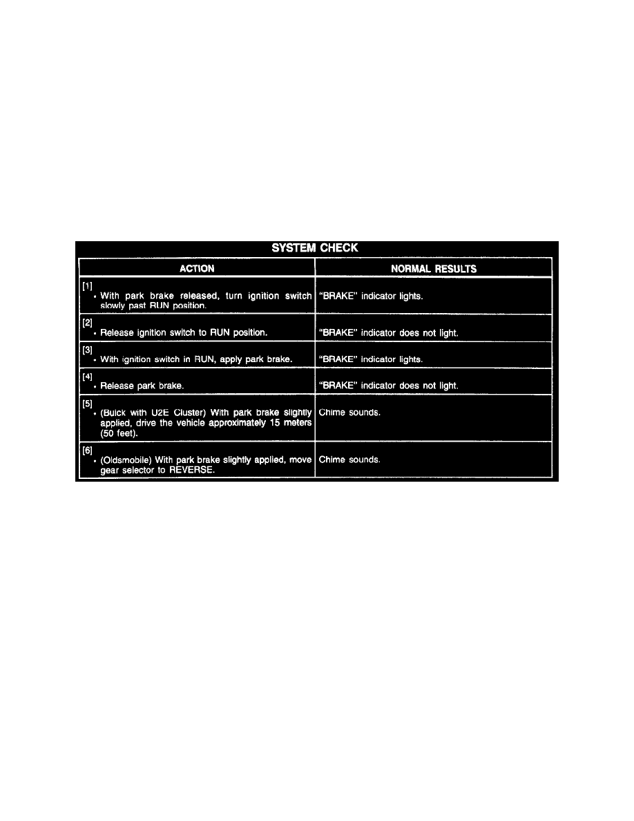
System Check
Troubleshooting Hints
PERFORM BEFORE BEGINNING SYSTEM DIAGNOSIS
1. Check Fuse 1D in I/P Fuse Block and Fuse 8 in RH I/P Power Distribution Center by visual inspection.
2. Check for a broken (or partially broken) wire inside of the insulation which could cause system failure but prove good in a continuity/voltage
check. (Refer to Troubleshooting Procedures.)
3. Check for proper installation of aftermarket electronic equipment which may affect the integrity of other systems. (Refer to Troubleshooting
Procedures.)
4. Before component replacement, check for poor terminal contact at component connectors and in-line harness connectors; refer to
Troubleshooting Procedures. See: Diagrams/Diagnostic Aids