
LSS V6-3.8L VIN K (1997)
Crankshaft Position Sensor: Service and Repair
Crankshaft Position Sensor
REMOVAL PROCEDURE
1. Disconnect the negative battery cable.
2. Remove the serpentine belt(s) from the crankshaft pulley.
3. Raise the vehicle on a hoist.
4. Remove the right front wheel and tire assembly.
5. Remove the right inner fender access cover.
6. Hold the flywheel with J 37096 or equivalent Flywheel Holding Tool.
7. Using 28 mm socket, remove the crankshaft harmonic balancer retaining bolt.
8. Remove the crankshaft harmonic balancer using special tool J 38197 or equivalent Balancer Remover. (Do Not use a pry bar)
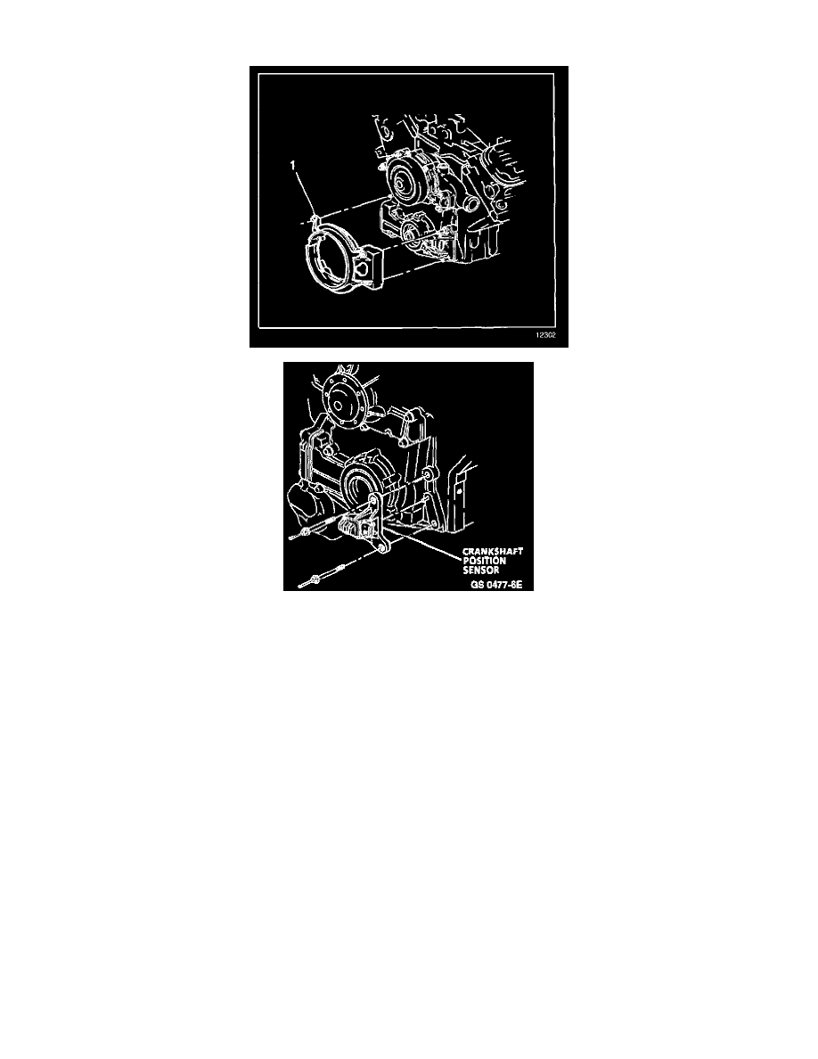
9. Remove the crankshaft position sensor shield
10. Disconnect the sensor electrical connector.
11. Remove 2 attaching bolts from the crankshaft position sensor.
12. Remove the crankshaft position sensor from block face.
INSTALLATION PROCEDURE
1. Position the crankshaft position (CKP) sensor to the block.
2. Install the bolts to hold the CKP sensor to the block face.
-
Tighten the bolts to 20-40 Nm (14-28 lb ft).
3. Install the crankshaft position sensor shield.
4. Connect the CKP sensor electrical connector.
5. Position the crankshaft harmonic balancer on the crankshaft.
6. Hold the flywheel with J 37096 or equivalent Flywheel Holding Tool.
-
Using J 36660 or equivalent Torque/Angle Meter, tighten the harmonic balancer bolt to 150 Nm +76 degrees (111 lb ft +76 degrees).
7. Install the right inner fender access cover.
8. Install the right front wheel and tire assembly.