
LSS V6-3.8L VIN K (1997)
Throttle Position Sensor: Description and Operation
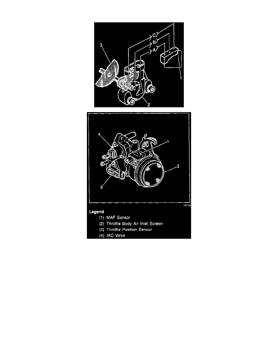
The Throttle Position (TP) sensor is a potentiometer connected to the throttle shaft on the throttle body. By monitoring the voltage on the signal
line, the PCM calculates throttle position. As the throttle valve angle is changed (accelerator pedal moved), the TP sensor signal also changes. At a
closed throttle position, the output of the TP sensor is low. As the throttle valve opens the TP sensor voltage increases so that at Wide Open
Throttle (WOT), the TP sensor voltage should be above 4 volts. The PCM calculates fuel delivery based on throttle valve angle (driver demand).
A broken or loose TP sensor may cause intermittent bursts of fuel from an injector and unstable idle because the PCM thinks the throttle is
moving. A hard failure in the TP sensor 5 volts reference or signal circuits should set either a DTC P0122 or DTC P0123. A hard failure with the
TP sensor ground circuit may set DTCs P0123 and P0117. Once a DTC is set, the PCM will use an artificial default value based on engine RPM
and mass air flow for throttle position and some vehicle performance will return. A high idle may result when either DTC P0122 or DTC P0123 is
set.
The PCM can detect intermittent TP sensor faults. DTC P1121 or DTC P1l22 will set if an intermittent high or low circuit failure is being
detected. The PCM can also detect a shifted TP sensor. The PCM monitors throttle position and compares the actual TP sensor reading to a
predicted TP value calculated from engine speed. If the PCM detects an out of range condition, DTC POl2l will be set.