
LSS V6-3.8L VIN K (1997)
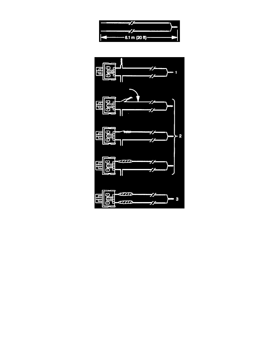
Figure 35
Figure 36
Figure 37
CAUTION: When you are deploying an inflator module for disposal, perform the deployment procedures in the order listed:
^
Wear safety glasses throughout the procedures.
^
Make sure the area around the inflator module is clear of all people and loose or flammable objects.
^
Short the deployment harness wires as instructed.
^
Connect the deployment harness to the inflator module before you connect it to the power source.
^
Connect the deployment harness to the power source to immediately deploy the air bag.
Failure to follow the procedures in the order listed may result in personal injury.
16. Disconnect inflatable restraint I/P module, yellow 2-way connector. This connector is located above the RH sound insulator.
17. cut the inflatable restraint module harness connector from the vehicle. Leave at least 160 mm (6 inches) of wire at the connector (Figure 35).
18. Strip 13 mm (0.5 inches) of insulation from each wire lead of the connector (Figure 35).
19. Cut two 6.1 m (20 feet) deployment wires from 0.8 sq. mm (18 gauge) or thicker Multi-strand wire. Use these wires to fabricate the passenger
deployment harness.
20. Strip 13 mm (0.5 inches) of insulation from both ends of the wires cut in the previous step.
21. Short the wires by twisting together one end of each (Figure 36). The deployment wires shall remain shorted and not connected to a power source
until you are ready to deployed the air bag.