
Ninety-Eight V6-252 4.1L VIN 4 4-BBL (1982)
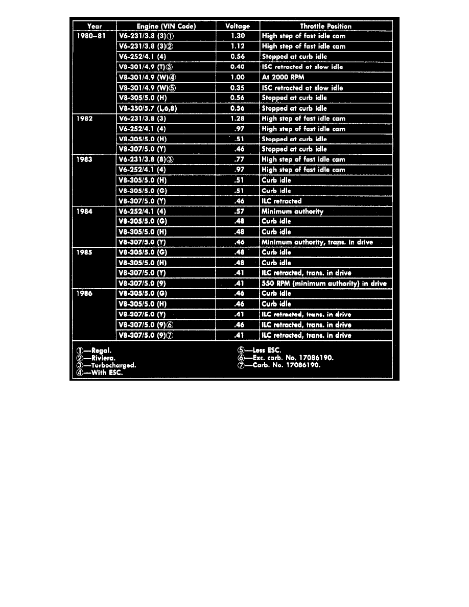
Fig. 27 Throttle Position Sensor (TPS) adjustment specifications.
NOTE: Do not remove plug sealing TPS adjustment or adjust TPS unless carburetor is overhauled or "Computer Command Control (C3)" system
diagnosis indicates a problem with the switch.
1. Drill a .078 (5/64) inch hole, 1/16-1/8 inch deep, in plug covering TPS adjustment, Fig. 24.
2. Thread a No. 8 sheet metal screw into hole and pry out plug using a suitable lever.
3. Remove TPS adjusting screw using tool J-28696 or equivalent.
4. Leaving electrical connector in place, connect a digital voltmeter between TPS center terminal (B) and bottom terminal (C), using jumper wires if
necessary. Only a digital voltmeter with 10 megohm input impedance or higher can be used. Conventional voltmeters do not have
sufficient resistance to obtain accurate readings.
5. With ignition on, engine stopped and A/C off, install TPS screw and adjust quickly to obtain specified TPS idle voltage, Fig. 27.
6. Turn ignition off and install new plug over TPS adjusting screw.