
Ninety-Eight V6-3800 3.8L (1989)
Dual Crankshaft Sensor: Service and Repair
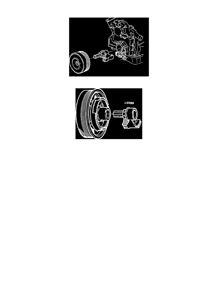
Crankshaft Sensor Positioning
Special Tool; Assembly
*** UPDATED BY TSB #91-6E-5 DATE: 11/90
The harmonic balancer on these engines is now press fit on to the crankshaft and requires the use of tool J-38197 for removal. The torque specification to
be used during installation has also been revised from what was originally published. The procedure to be used when replacing the crank sensor is as
follows:
REMOVAL:
1.
Disconnect the serpentine belt from the crankshaft pulley.
2.
Raise the vehicle on the hoist.
3.
Remove the right front tire and wheel assembly.
4.
Remove the right inner fender access cover.
5.
Using a 28 mm socket, remove the crankshaft harmonic balancer retaining bolt.
6.
Remove the crankshaft harmonic balancer using tool J-38197.
7.
Remove the foreign object deflector (DO NOT use a pry bar).
8.
Disconnect the sensor electrical connector.
9.
Remove the sensor and pedestal from the block face.
10.
Remove the sensor from the pedestal.
INSTALLATION: