
Ninety-Eight V6-3800 3.8L Supercharged (1993)
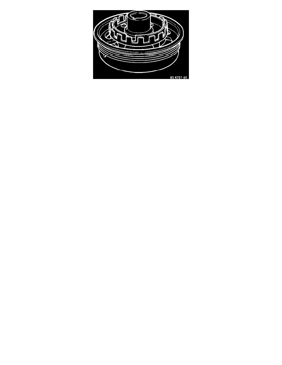
Harmonic Balancer W/Interrupter Rings
The piece of steel is two concentric interrupt rings mounted to the rear of the crankshaft balancer. Each interrupter ring has blades and windows that,
with crankshaft rotation, either block the magnetic field or let it pass to one of the Hall-effect switches. The outer Hall-Effect switch is called the 18X
crank sensor because this outer interrupt ring has 18 evenly spaced blades and windows which are all the same width. The 18X crank sensor produces
18 "ON-OFF" pulses per crankshaft revolution. The Hall-effect switch closest to the crankshaft is called the 3X crank sensor because it has 3 different
unevenly spaced and different width size windows. The 3X crank sensor produces 3 different length "ON-OFF" pulses per crankshaft revolution. When
a 3X interrupter ring is between the magnet and the inner switch, the magnetic field will cause the 3X Hall switch to ground the 3X signal voltage
supplied from the C3I module. The 18X interrupt ring and Hall-effect switch react similarly. The C3I module interprets the 18X and 3X pulse signals as
an indication of crankshaft position, and must have both signals to fire the correct ignition coil. The C3I module determines crank position for correct
ignition coil sequencing by counting how many 18X signal transitions occur during a 3X pulse.