
Ninety-Eight V6-3800 3.8L Supercharged (1993)
Diode Markings
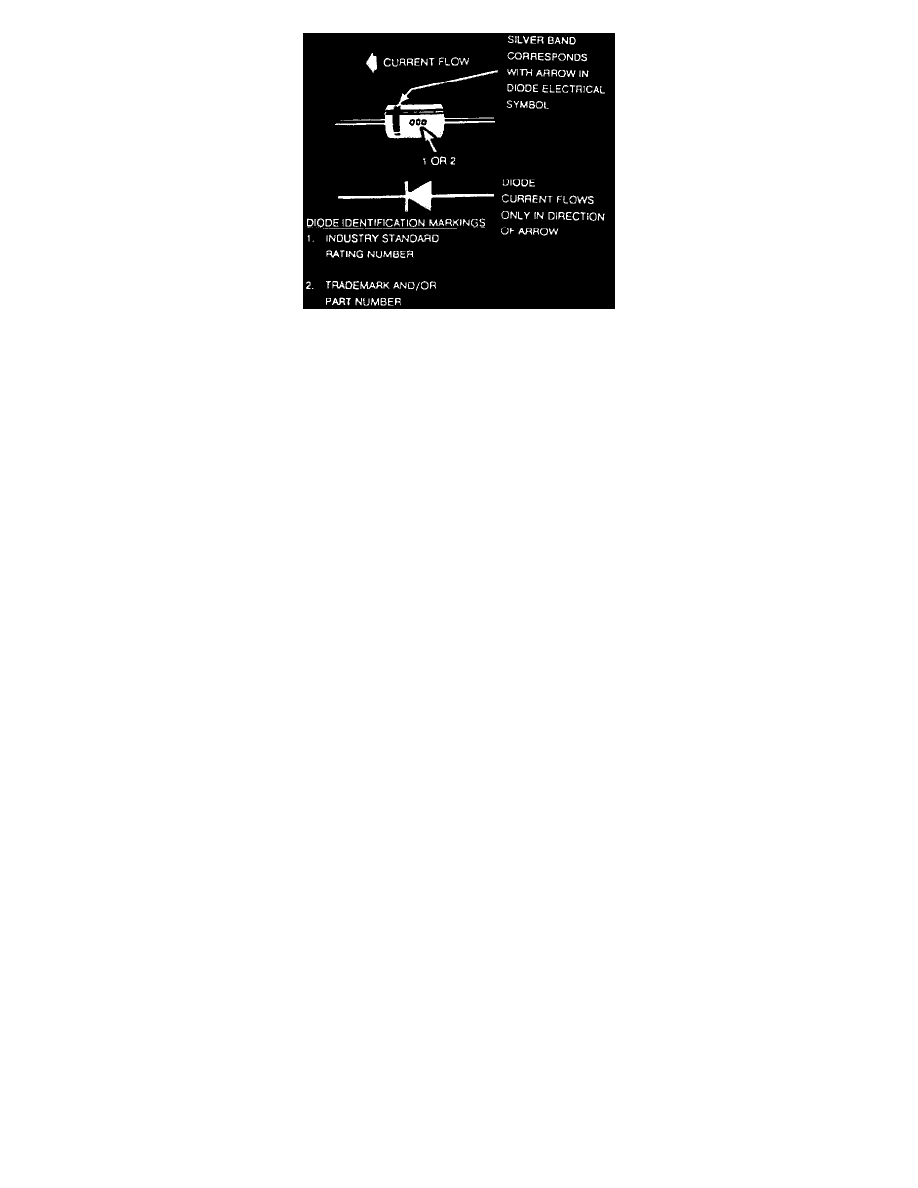
To identify the Peak Inverse Voltage (PIV) rating of the diode that will be replaced refer to illustration.
Replacement procedures are as follows:
1. If the diode is taped to the harness, remove all of the tape.
2. Paying attention to the direction of current flow, remove the faulty diode from the harness with a suitable soldering tool. If the diode is located
next to a connector terminal, remove the terminal(s) from the connector to prevent damage from the soldering tool.
3. Carefully strip away a section of insulation next to the old soldered portion of the wire(s). Do not remove any more than is necessary to attach
the new diode.
4. Check the current flow direction of the new diode, being sure to install the diode with the correct bias. Attach the new diode to the wire(s)
using 60/40 rosin core solder. Use a heat sink (aluminum alligator clip) attached across the diode leads to protect it from excessive heat.
Follow the manufacturer's instructions for the soldering equipment you are using.
5. Install terminal(s) into the connector body, if removed in step 2.
6. Tape the diode to the harness or connector using electrical tape. To prevent shorts to ground and water intrusion, completely cover all exposed
wire and diode attachment points.