
Ninety-Eight V6-3800 3.8L Supercharged (1993)
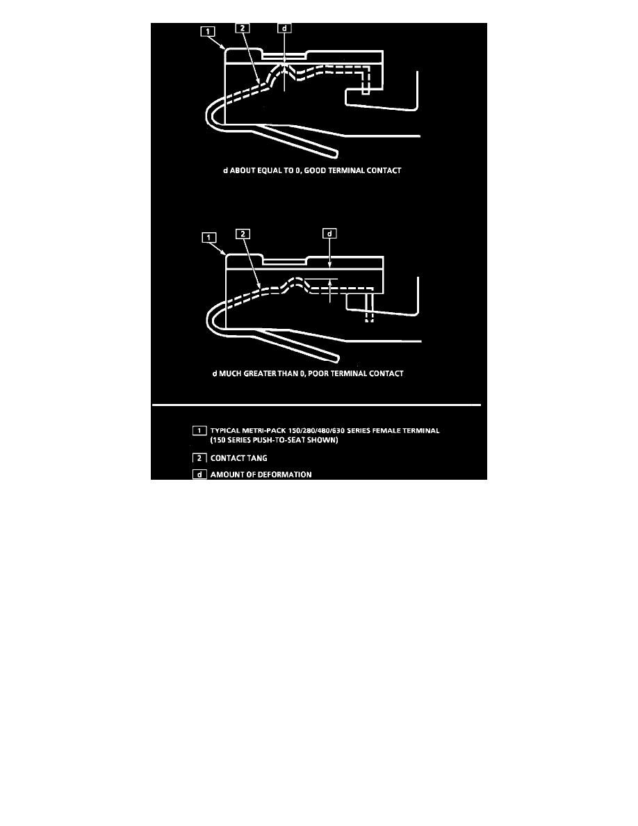
Fig. 7 Deformation of a Typical Metri-Pak Series Female Terminal
DESCRIPTION
When diagnosing an electrical system that utilizes Metri-Pack 150/280/480/630 series terminals (refer to GM Terminal Repair Kit, J 38125-A,
instruction manual, J 38125-4 for terminal identification), it is important to check terminal contact between a connector and component, or
between in-line connectors, before replacing a suspect component.
Frequently, a diagnostic chart leads to a step that reads: "Check for poor connection." Mating terminals must be inspected to assure good terminal
contact. A poor connection between the male and female terminal at a connector may be the result of contamination or deformation.
Contamination is caused by the connector halves being improperly connected, a missing or damaged connector seal, or damage to the connector
itself, exposing the terminals to moisture and dirt. Contamination, usually in underhood or underbody connectors, leads to terminal corrosion,
causing an open circuit or intermittently open circuit.
Deformation is caused by probing the mating side of a connector terminal without the proper adapter, improperly joining the connector halves or
repeatedly separating and joining the connector halves. Deformation, usually to the female terminal contact tang, can result in poor terminal
contact, see Fig. 7, causing an open or intermittently open circuit.
PROCEDURES:
Follow the procedure below to check terminal contact.
1. Separate the connector halves.
2. Inspect the connector halves for contamination. Contamination will result in a white or green build-up within the connector body or between
terminals, causing high terminal resistance, intermittent contact or an open circuit. An underhood or underbody connector that shows signs of
contamination should be replaced in its entirety: terminals, seals and connector body.