
Ninety-Eight FWD V6-181 3.0L (1985)
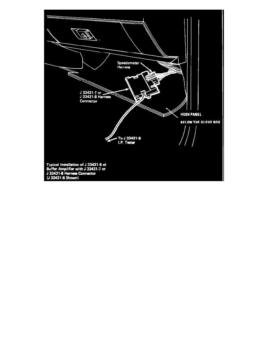
FIGURE 2
3.
To test the VEHICLE SPEED SENSOR BUFFER, remove both connectors from it and plug them into connector J-33431-8 of the I/P tester. See
Figure 2. With the tester set to "On", "54 mph", and "60 Hz" and the IGNITION SWITCH in "Run", the Speedometer should read 54 mph +/- 2
mph.
^
If the Speedometer reads correctly, the buffer is bad. Check for Battery voltage between terminal H (PNK/BLK) and terminal A (BLK/WHT)
of connector C1, with the IGNITION SWITCH in "Run". If this is correct, install a new VEHICLE SPEED SENSOR BUFFER.
^
If the Speedometer did not indicate correctly, continue to step 4.
4.
With the VEHICLE SPEED SENSOR BUFFER reconnected and the IGNITION SWITCH in "Run", backprobe terminal A (BLK/WHT) and C
(DK GRN) of connector C1 on the buffer. On the DC volts range, the voltage should be greater than 9 volts.
^
If the voltage is not above 9 volts, check the DK GRN 389 wire to the I/P connector C251 for a short or open.
^
If the voltage is above 9 volts, go to step 5.
5.
Check for Battery voltage supplied to the Speedometer circuit board. Remove the cluster and measure the voltage between terminals N and P of
cluster connector C251. Put the IGNITION SWITCH in "Run".
^
If Battery voltage is not present, check the PN K/BLK 39 wire and the BLK 150 wire for opens.
^
If Battery voltage is present, go to step 6.
6.
Inspect the printed circuit for faults between the cluster connector C251 and the speedometer circuit board. Measure the resistance between the
following terminals. There should be near zero ohms resistance.
C251
Terminal (Wire Color)
and
Resistance