
Ninety-Eight FWD V6-181 3.0L (1985)
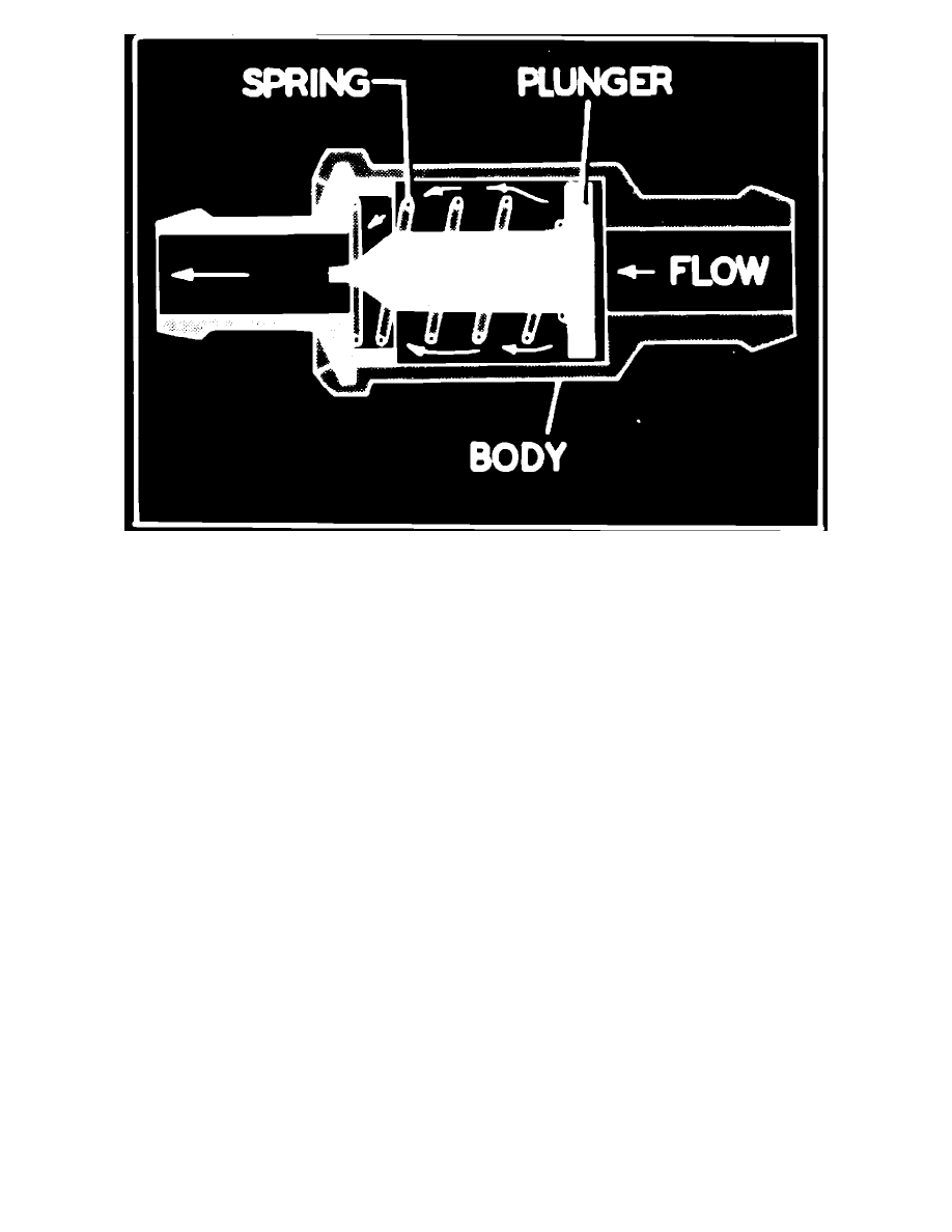
Fig. 32 Gasoline engine PCV valve. Cross sectional view
The gasoline engine PCV system, Fig. 31, prevents blow-by gases from escaping by routing them through a vacuum controlled ventilating valve and a
hose into the intake manifold. The blow-by gases mix with the air/fuel mixture and are burned in the combustion chambers. When the engine is running,
fresh air is drawn into the crankcase through a tube or hose connected to the air cleaner housing.
The PCV valve, Fig. 32, consists of a needle valve, spring and housing. When the engine is off, the spring holds the needle valve closed to stop vapors
from entering the intake manifold. When the engine is running, manifold vacuum unseats the valve allowing crankcase vapors to enter the intake
manifold. In case of a backfire in the intake manifold, the valve closes, stopping the backflow and preventing ignition of fumes in the crankcase. During
certain engine conditions, more blow-by gases are created than the ventilator valve can handle. The excess is returned through the air intake tube to the
air cleaner and carburetor where it is burned in the engine.