
Ninety-Eight FWD V6-181 3.0L (1985)
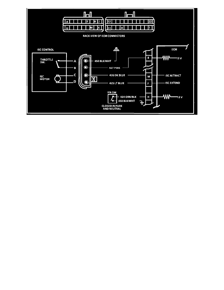
- Wiring Diagram for Chart C-2A Idle Speed Control (ISC) Check.
CHART C-2A, IDLE SPEED CONTROL
CIRCUIT DESCRIPTION
Idle speed control is performed by an ISC assembly controlled by the ECM. When the throttle is contacting the plunger, a circuit to ground is
completed thru terminal 'B' of the ISC and is sensed by the ECM. Grounding the diagnostic "test" terminal in the ALCL connector with the Ignition
"ON" and engine stopped causes the ISC plunger to pulse "IN" and "OUT" unless the ISC switch circuit is open. In this case, the plunger will move, but
not smoothly. It will jump or snap.
CHART DESCRIPTION
1.
This is a functional test for ECM to cycle ISC in both directions by grounding the test terminal.
2.
Functional test for ISC plunger switch. Light should go "ON" when plunger is depressed.
3.
Checks for open in CKT. 427 to ISC. Low or no voltage indicates an open to the ECM, faulty ECM or poor ground. Voltage should be near
battery voltage.
4.
Manually applies voltage to the ISC motor to determine if fault is in motor.
5.
Checks for faulty P/N switch CKT. 434. In park or neutral, voltage is normally low, and in drive ranges voltage goes to near battery voltage.