
Ninety-Eight FWD V6-260 4.3L DSL (1985)
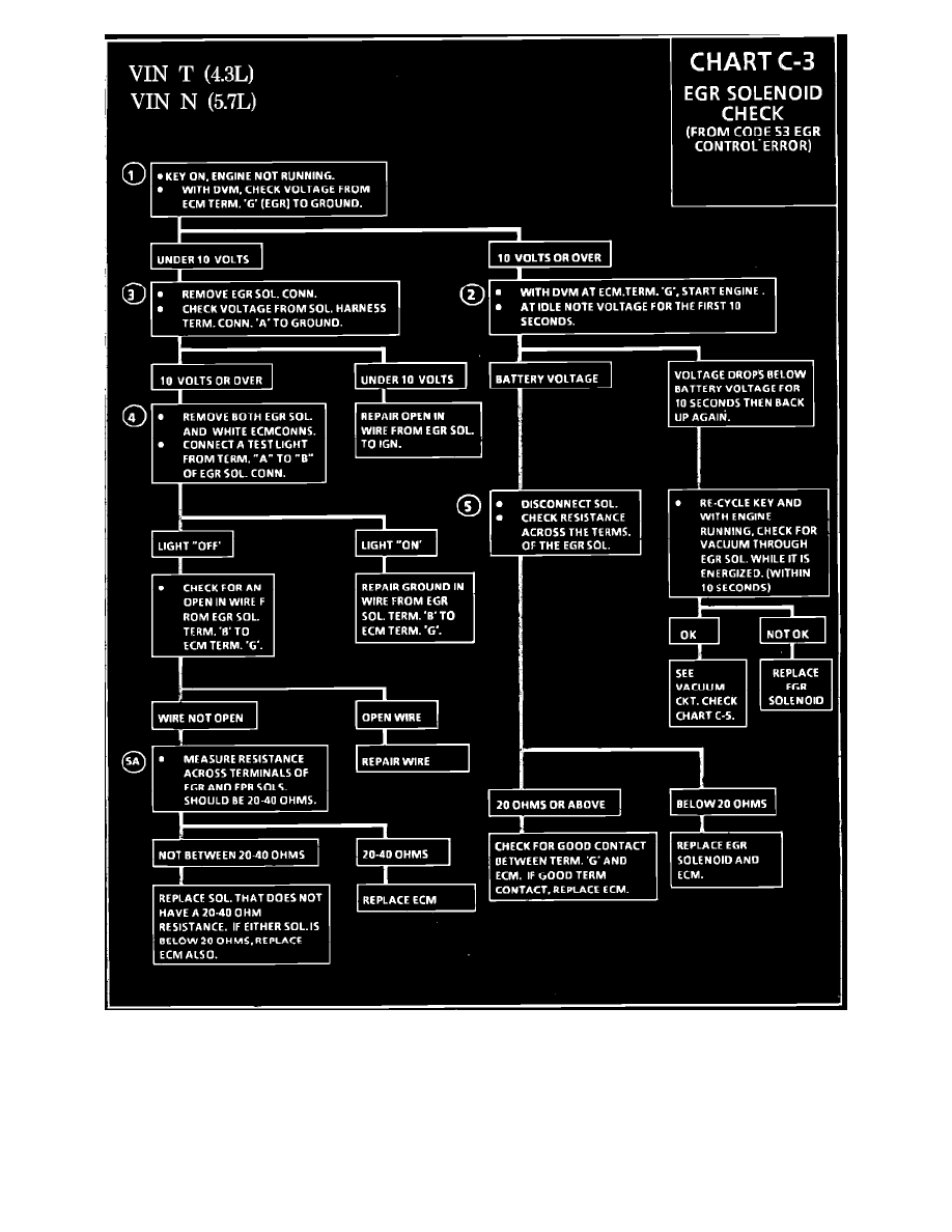
Fig. 029 - Chart C-3 EGR Solenoid Check.
1.
Checks for ignition voltage to Terminal "G" of ECM. Normal reading will be battery voltage. (10 volts or over)
2.
Checks for ignition voltage to EGR solenoid. Should normally be battery voltage.
3.
This checks for EGR control by the ECM. With the engine at idle, the voltage will drop below battery voltage as the PWM solenoid cycles. If
voltage falls for 10 seconds, then goes back to battery voltage, the ECM has recognized a vacuum error and has shut the EGR "OFF". Constant
battery voltage indicates no ECM control. Normal voltage is battery voltage with key "ON", and below battery voltage and varying, with the
engine at idle.
4.
Checks for a grounded wire between ECM and EGR solenoid. Test light should normally be "OFF".