
Silhouette V6-191 3.1L VIN D TBI (1995)
Untwist the conductors. Then, prepare the splice by following the splicing instructions for copper wire presented earlier. Remember to stagger
splices to avoid shorts, Fig. 16.
Step 4: Re-assemble the Cable
Fig. 17 The Re-assembled Cable
After you have spliced and taped each wire, rewrap the conductors with the mylar tape. Be careful to avoid wrapping the drain wire in the tape.
Next, splice the drain wire following the splicing instructions for copper wire. Then, wrap the drain wire around the conductors and mylar tape,
Fig. 17.
Step 5: Tape the Cable
Fig. 18 Proper Taping
Tape over the entire cable using a winding motion, Fig. 18. This tape will replace the section of the jacket you removed to make the repair.
Weather Pack Connectors
WEATHER PACK
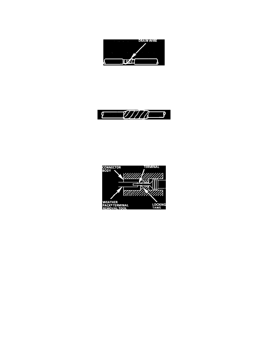
Fig. 21 Typical Weather Pack Connector and Terminal
Follow the steps below to repair Weather Pack(R) connectors, Fig. 21.
Step 1:
Separate the connector halves.
Step 2:
Open secondary lock. A secondary lock aids in terminal retention and is usually molded to the connector.
Step 3:
Grasp the lead and push the terminal to the forward most position. Hold the lead at this position.
Step 4:
Insert the Weather Pack(R) terminal removal tool into the front (mating end) of the connector cavity until it rests on the cavity shoulder.
Step 5:
Gently pull on the lead to remove the terminal through the back of the connector.
NOTICE: Never use force to remove a terminal from a connector.
Step 6:
Inspect the terminal and connector for damage. Repair as necessary, see TERMINAL REPAIR.
Step 7:
Reform the lock tang and reseat terminal in connector body.
Step 8:
Close secondary locks and join connector halves.
Additional Information
NOTE: Turn OFF power to the test circuit before attempting in-circuit resistance measurements to prevent false readings or damage to the meter. Do