
Silhouette V6-191 3.1L VIN D TBI (1995)
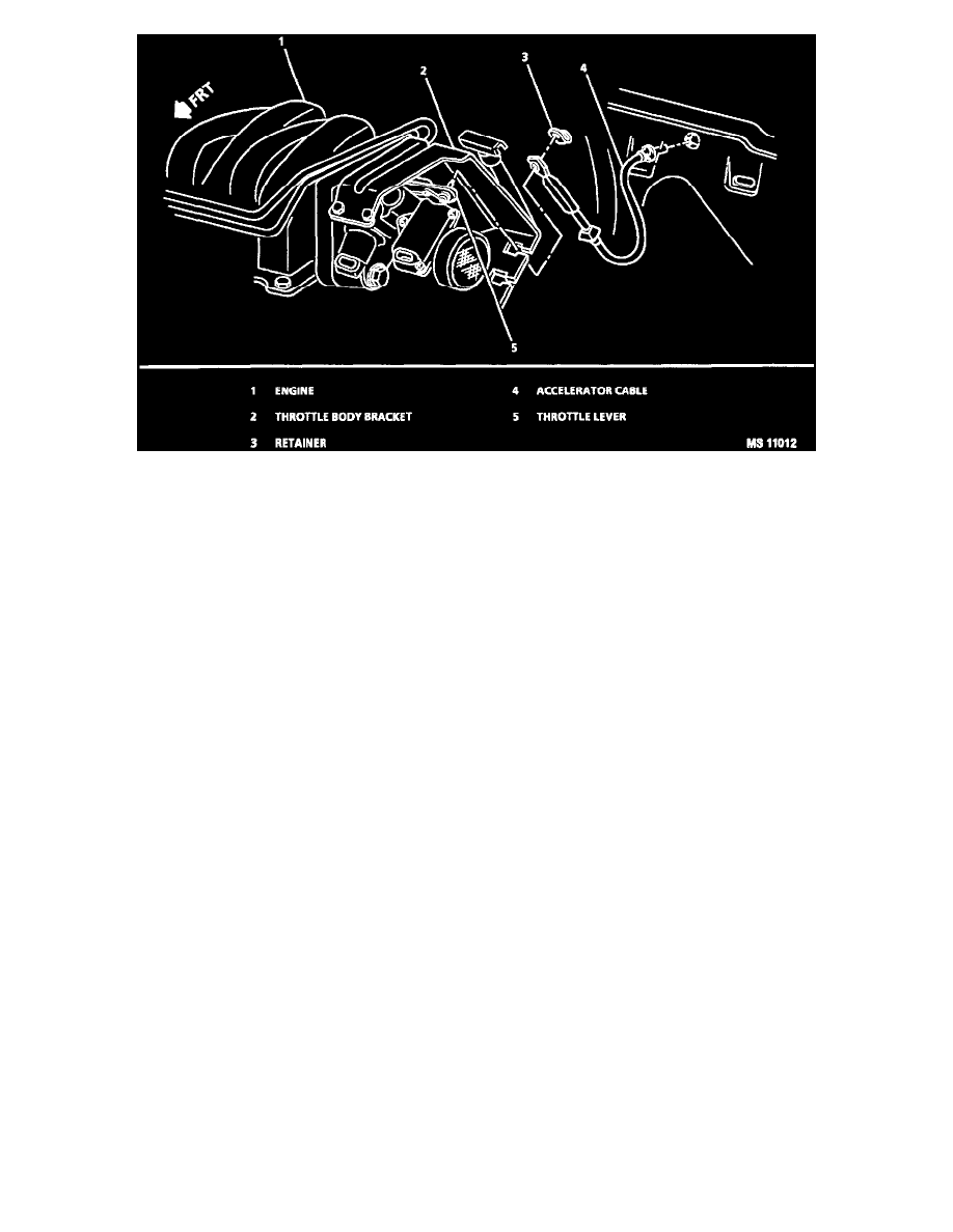
Accelerator Controls
REMOVE OR DISCONNECT
1. Lower instrument panel trim attaching screws and clip.
^
Partially drop lower instrument panel trim and disconnect courtesy light.
2. Accelerator cable from accelerator pedal.
3. Stop switch electrical connectors.
4. Vacuum hose and cruise control switch electrical connector (only on vehicles equipped with cruise control).
5. Brake rod attaching nut, washer and rod from brake pedal.
6. Accelerator/brake pedal bracket, attaching nuts screw and accelerator/brake pedal bracket.
^
Support master cylinder and power booster assembly.
INSTALL OR CONNECT
CAUTION
^
Use care when pressing the retainer into hole in rod to ensure that the cable is not kinked or damaged in any way.
^
To prevent possible interference, flexible components (hoses, wires, conduits, etc.) must not be routed within 50 mm (2") of moving parts
unless routing is positively controlled.
^
Wire, hoses, cables or other obstructions must not be placed within 13 mm (1/2") of cable or rod at any point in their travel.
1. Reverse removal procedure. Use new lock nuts when installing the accelerator/brake pedal bracket.
Tighten
^
Accelerator pedal bracket attaching nuts (2) to 21 Nm (15 lb. ft.).
^
Accelerator/brake pedal bracket attaching bolt to 25 Nm (18 lb. ft.).
^
Brake rod attaching nut to 43 Nm (32 lb. ft).
Inspect
^
Check for complete throttle opening and closing by operating accelerator pedal. Also check for poor carpet fit under the accelerator pedal.
Throttle should operate freely without bind between full closed and wide open throttle.
2. Adjust stop light switch and cruise control switch (only on vehicles equipped with cruise control).