
Silhouette V6-191 3.1L VIN D TBI (1995)
Fuel System Routing Diagram (Part 3 Of 3)
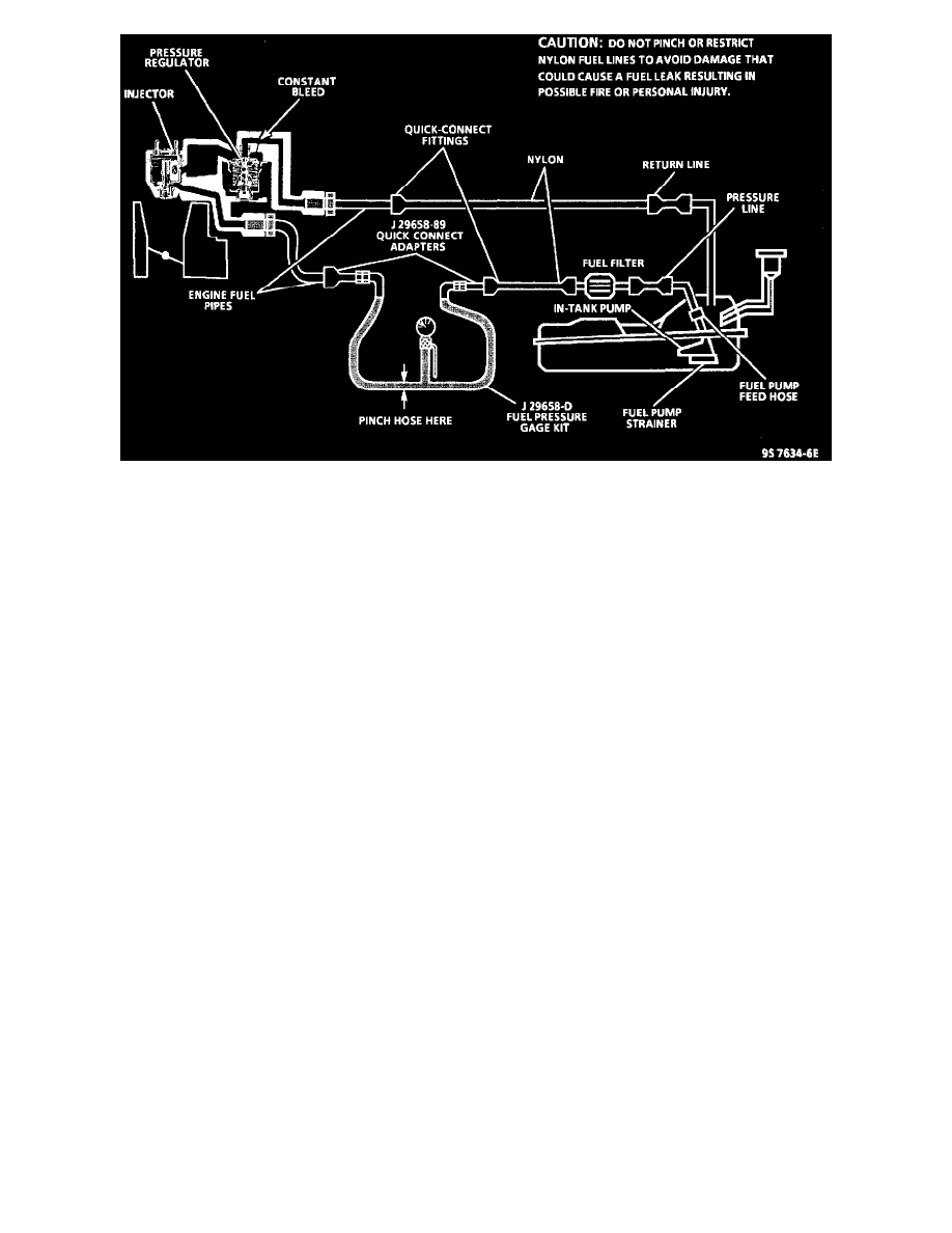
SYSTEM DESCRIPTION
When the ignition switch is turned "ON," the Powertrain Control Module (PCM) will turn "ON" the in-tank fuel pump. It will remain "ON" as
long as the engine is cranking or running if there is oil pressure, and the PCM is receiving reference pulses. If there are no reference pulses, the
PCM will shut "OFF" the fuel pump within 2 seconds after ignition "ON" or engine stops.
An electric fuel pump, attached to the fuel sender assembly (inside the fuel tank), supplies fuel through an in-line filter to the TBI unit. The pump
is designed to provide sufficient fuel flow for all engine demands. A pressure regulator, attached to the fuel meter cover, keeps fuel available to the
injectors at a regulated pressure. Unused fuel is returned to the fuel tank by a separate line.
The fuel pump "test" connector is located on the driver's side of the engine compartment.
CHART TEST DESCRIPTION
Number(s) below refer to circled number(s) on the diagnostic chart.
1. Install fuel pressure gauge. Fuel pressure should be noted with the fuel pump running. When fuel pump stops running, fuel pressure will drop
immediately through a constant bleed passage machined in the fuel meter cover.
2. This step checks the operation of the fuel pump relay circuit. Observing the fuel pressure gauge when ignition is cycled "ON," pressure should
build when fuel pump is running and drop when pump stops.
3. This check will verify the operation of the fuel pump check valve. A leaking check valve will cause fuel in the pressure (feed) line to drain back to
the tank and result in long crank times. The amount of pressure is not important as long as some pressure is maintained.
4. Fuel pressure that drops off during acceleration, cruise or hard cornering may cause a lean condition and result in a loss of power, surging or
misfire. This condition can be diagnosed using a Tech 1 scan tool. If the fuel system is very lean, the oxygen sensor will stop toggling and output
voltage will drop below 500 mV. Also, injector pulse width will increase.
5. Fuel pressure below 62 kPa (9 psi) may cause a lean condition and may set a Diagnostic Trouble Code (DTC) 44 or a DTC 32. Driveability
conditions can include hard starting cold, hesitation, poor driveability, lack of power, surging or misfire.
6. Restricting fuel flow as directed causes fuel pressure to build above regulated pressure. With battery voltage applied to the fuel pump "test"
connector, pressure should rise above 90 kPa (13 psi) as the gauge outlet hose is pinched.
7. Fuel pressure above 90 kPa (13 psi) may cause a rich condition and may set a DTC 45. Driveability conditions can include hard starting (followed
by black smoke) and a strong sulfur smell in the exhaust.
8. This test determines if the high fuel pressure is due to a restricted fuel return line or a faulty fuel pressure regulator.