
Silhouette V6-191 3.1L VIN D TBI (1995)
Throttle Position Sensor: Description and Operation
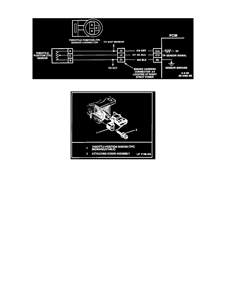
Throttle Position (TP) Sensor Schematic
Throttle Position Sensor
The Throttle Position (TP) sensor is connected to the throttle shaft on the TBI unit. It is a potentiometer with one end connected to 5 volts from
the Powertrain Control Module (PCM) and the other to ground. A third wire is connected to the PCM to measure the voltage from the TP sensor.
As the throttle valve angle is changed (accelerator pedal moved), the output of the TP sensor also changes. At a closed throttle position, the output
of the TP sensor is low (approximately 0.5 volt). As the throttle valve opens, the output increases so that, at wide-open throttle, the output voltage
should be approximately 5 volts.
By monitoring the output voltage from the TP sensor, the PCM can determine fuel delivery based on throttle blade angle (driver demand). If the
sensor CKT is open, the PCM will set a Diagnostic Trouble Code (DTC) 22. If the circuit is shorted, the PCM will think the vehicle is at Wide
Open Throttle (WOT), and a Diagnostic Trouble Code (DTC) 21 will be set. A broken or loose TP sensor can cause intermittent bursts of fuel
from the injector, and an unstable idle, because the PCM thinks the throttle is moving. Once a diagnostic trouble code is set, the PCM will use an
artificial value for TP sensor and some vehicle performance will return.
On all engines, the TP sensor is not adjustable. The PCM uses the reading at idle for the zero reading, so no adjustment is necessary.