
Silhouette V6-191 3.1L VIN D TBI (1995)
Knock Sensor: Description and Operation
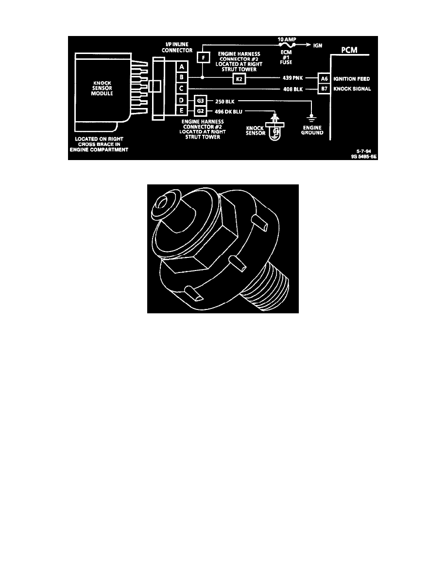
Knock Sensor Wiring Schematic
PURPOSE
To control spark knock, a Knock Sensor (KS) system has been added. This system is designed to retard spark timing up to 8°, to reduce spark
knock in the engine. This allows the engine to use maximum spark advance to improve driveability and fuel economy.
Varying octane levels in gasoline can cause detonation in engines. Detonation is also known as spark knock.
OPERATION
The KS system has two major components:
^
KS Module.
^
Knock Sensor.
The sensor is mounted in the engine block below the right bank of cylinders. When the KS knock sensor detects abnormal vibration (spark knocking)
in the engine, it produces a voltage that is received by the KS module. As long as the KS module sees no voltage from the knock sensor (knock not
present), it sends a signal voltage (8 to 10 volts) to the Powertrain Control Module (PCM) and the PCM provides normal spark advance.
When the module detects voltage from the knock sensor (knock present), it turns "OFF" the signal to the PCM and the voltage at terminal "B7" goes
to 0 volt. The PCM then retards Ignition Control (IC) timing to reduce spark knock.