
Silhouette V6-191 3.1L VIN D TBI (1995)
Knock Sensor: Testing and Inspection
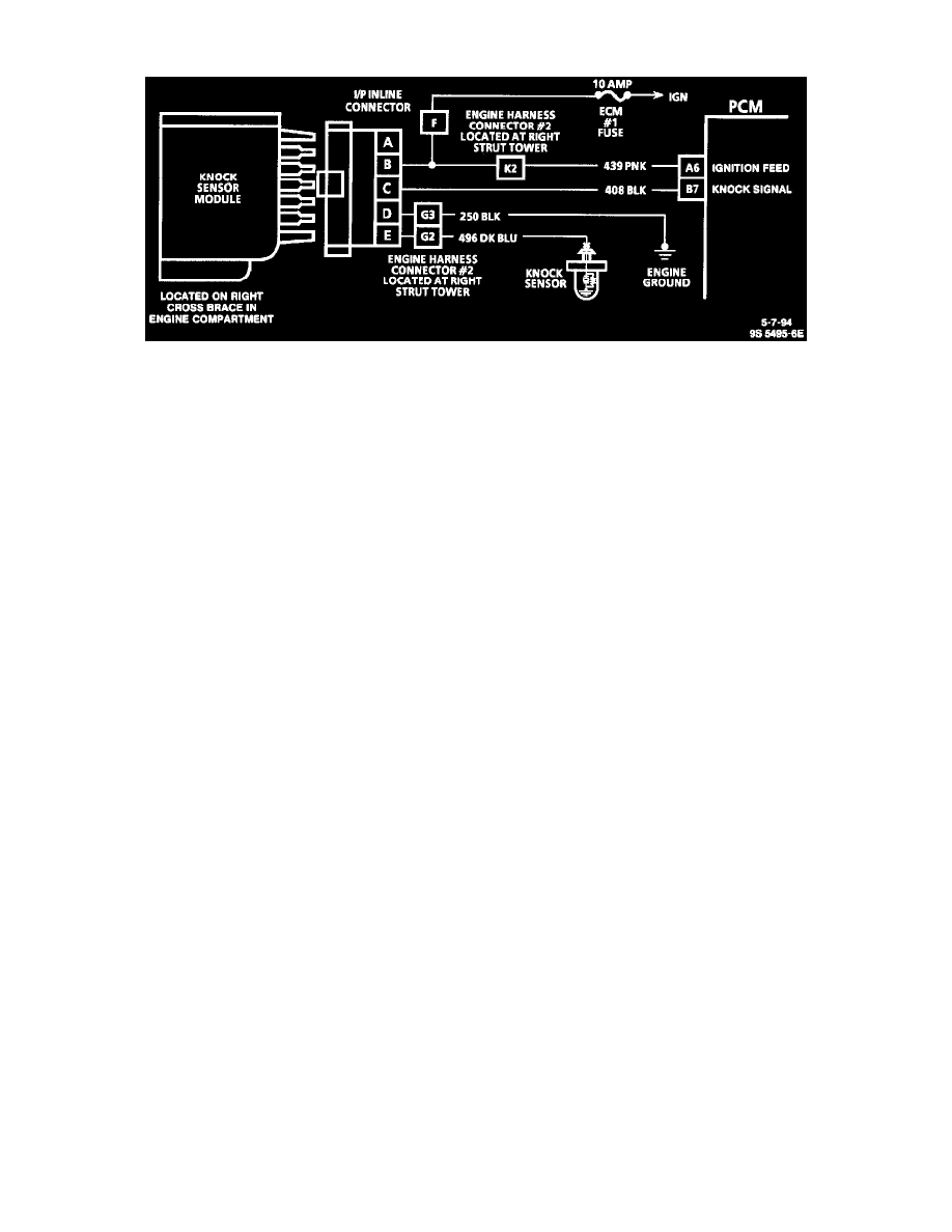
Knock Sensor Wiring Schematic
A Tech 1 scan tool will indicate when the knock sensor module signals the Powertrain Control Module (PCM) that knock is present. Refer to C
Charts/Chart C-5 Knock Sensor System Check for further information on the KS system. See: Powertrain Management/Computers and Control
Systems/Testing and Inspection/Diagnostic Trouble Code Tests and Associated Procedures/Related Tests and Information/C Charts/Chart C-5
Knock Sensor (KS) System Check
RESULTS OF INCORRECT KS OPERATION
Loss of the knock sensor signal or loss of ground at KS module would cause the signal to the PCM to remain high. This condition would cause the
PCM to control Ignition Control (IC), as if no spark knocking were happening. No retard would occur and spark knocking could become severe
under heavy engine load conditions.
Loss of the KS signal to the PCM would cause the PCM to constantly retard IC. This could result in sluggish performance and cause a DTC 43 to
set.
Tech 1 scan tools indicate presence of knock by displaying "Yes" (knock present), or "No" (knock not present). If DTC 43 is present, use that
chart to diagnose the system.