
Silhouette FWD V6-3.4L VIN E (2004)
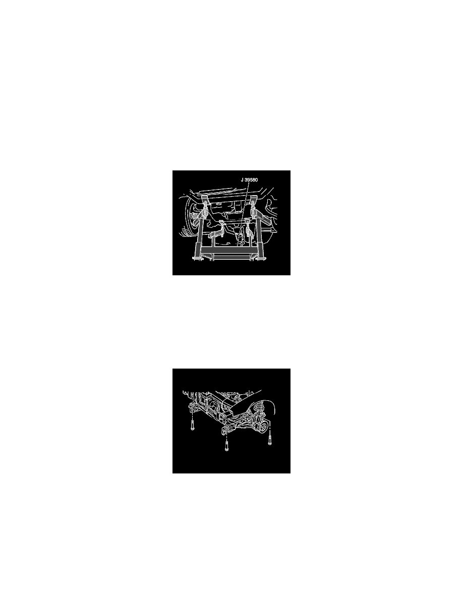
23. Remove the frame rear bolts.
24. Raise the vehicle in order to separate the frame from the vehicle.
25. If you are REPLACING the frame, perform the following steps:
1. Remove the frame insulators from the frame. Refer to Frame Cushion or Insulator Replacement - Front (See: Front Subframe Mount/Service
and Repair/Frame Cushion or Insulator Replacement - Front) .
2. Remove the lower control arms from the frame. Refer to Lower Control Arm Replacement in Front Suspension.
Installation Procedure
1. If you are REPLACING the frame, perform the following steps:
1. Install the lower control arms to the frame. Refer to Lower Control Arm Replacement in Front Suspension.
2. Install the frame insulators to the frame. Refer to Frame Cushion or Insulator Replacement - Front (See: Front Subframe Mount/Service and
Repair/Frame Cushion or Insulator Replacement - Front) .
2. Position the transaxle table with the frame under the vehicle.
Important: Ensure that the power steering cooler line does not become trapped by the engine mount during this step.
3. Lower the vehicle until the frame is close to the vehicle.
4. Adjust the utility straps as necessary in order to align the powertrain mounts with the frame.
Important: Ensure that the alignment pins remain installed during the frame installation.
5. Inserting two 19 mm (0.75 in) diameter X 203 mm (8.0 in) long guide pins or drill bits into the frame right side alignment holes in order to align
the frame.
Notice: Refer to Fastener Notice in Cautions and Notices.
6. Install the frame front bolts.
Tighten the bolts to 150 N.m (111 lb ft).
7. Install the frame rear bolts.
Tighten the bolts to 165 N.m (122 lb ft).
8. Remove the alignment pins from the frame.