
Toronado V6-3800 3.8L (1988)
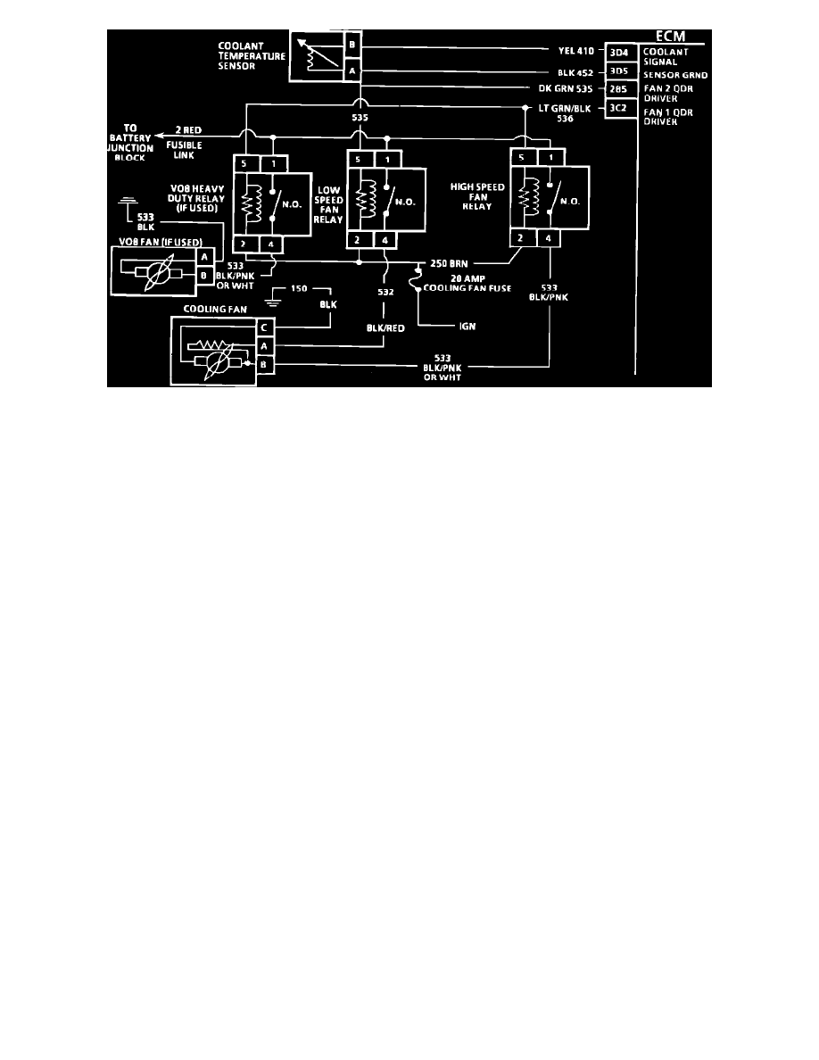
Chart C-12A Wiring Diagram
CIRCUIT DESCRIPTION:
On standard cooling applications, one fan, one low speed relay and one high speed relay are used. On V08 (Heavy Duty Cooling) systems, the two
coolant fans are energized through one low speed and two high speed relays.
Power for the fan(s) comes through the fusible link to terminal "1" on all relays. The relays are energized when current flows to ground through the ECM
or A/C pressure switch.
Low Speed Relay - The "LO" speed relay is energized by the ECM. The ECM energizes the relay through terminal 2B5 when the coolant temperature
reaches 98°C (208°F).
High Speed Relay - If the A/C refrigerant pressure reaches 275.0 psi (1896.0 kPa), the A/C pressure switch closes and the high speed fan relay is
energized. The ECM also controls the high speed fan relay when coolant temperature exceeds 108°C.
Pusher Fan Relay - The pusher fan is installed as part of the heavy duty cooling package (V08) and is turned "ON" anytime the high speed fan is running.
TEST DESCRIPTION: Numbers below refer to circled numbers on the diagnostic chart.
1.
Codes E014 or E015 could mean coolant system or Sensor operation is not normal so fan(s) operation can't be checked correctly.
2.
ECM output E009 grounds "LO" speed relay through the ECM for 3.0 seconds "ON" and 3.0 seconds "OFF." "LO" speed fan should be "ON" for
3.0 seconds and "OFF" for 3.0 seconds.
3.
Grounding A/C pressure switch harness terminal "B" should energize high speed relay and fan should run in high speed.