
Toronado V6-3800 3.8L (1988)
Wiring Diagram for Chart A-7 - Fuel System Pressure Test
CIRCUIT DESCRIPTION:
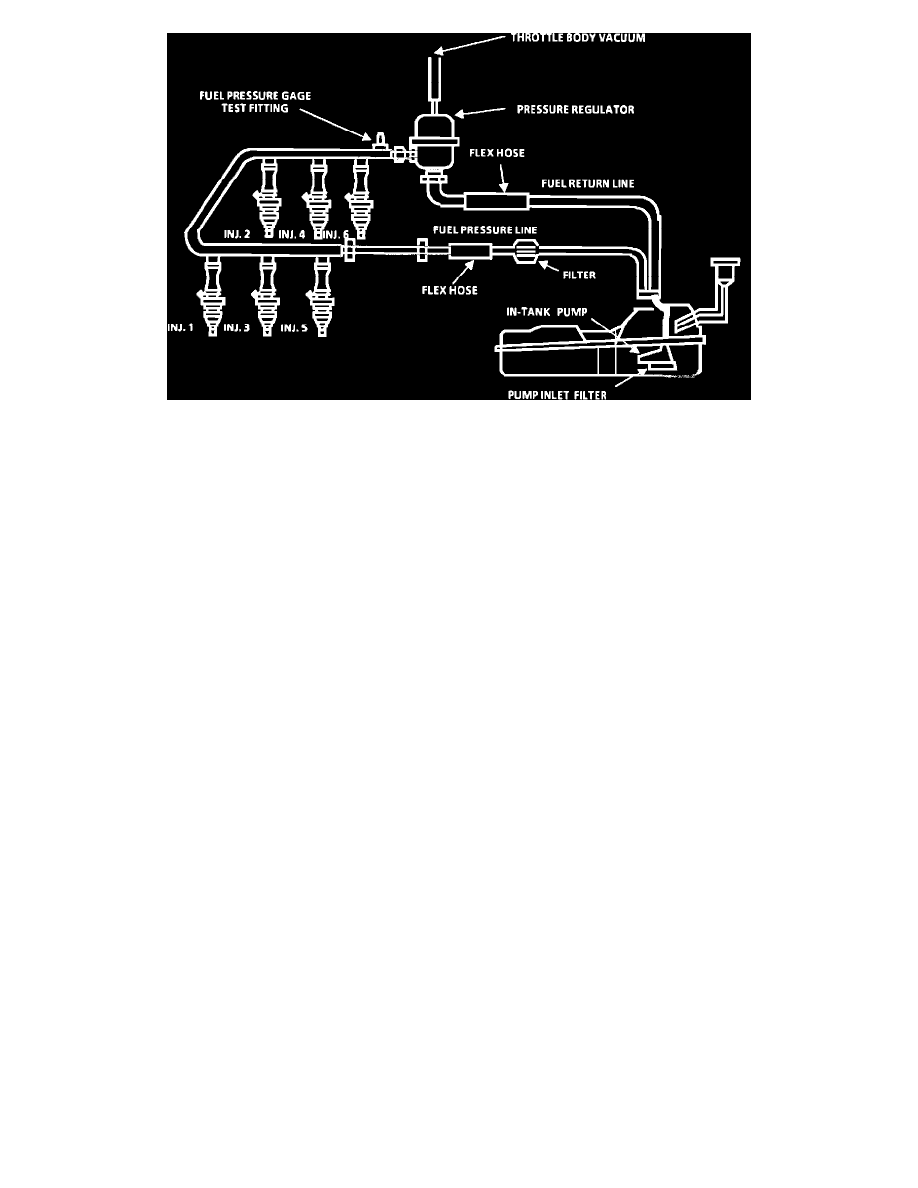
The fuel pump will deliver fuel to the fuel rail and injectors, then to the pressure regulator, where the system pressure is controlled. Excess fuel pressure
is bypassed back to the fuel tank. When the engine is stopped, the pump can be turned "ON" by applying battery voltage to the test terminal located in
the engine compartment. Improper fuel system pressure may contribute to one or all of the following symptoms:
^
Cranks but won't run.
^
Code E044 or E045.
TEST DESCRIPTION: Numbers below refer to circled numbers on the diagnostic chart.
CAUTION: To reduce the risk of fire and personal injury, it is necessary to relieve the fuel system pressure before servicing fuel system components.
To do this:
^
Disconnect the fuel tank harness connector.
^
Crank engine - engine will start and run until fuel supply remaining in fuel pipes is consumed.
^
Engage starter for 3.0 seconds to assure relief of any remaining pressure.
1.
Install pressure gage J-34730-1 to fuel pressure tap.
^
Connect the fuel tank harness connector.
^
Start engine. With ignition "ON," pump pressure is controlled by spring pressure and throttle body vacuum within the pressure regulator
assembly.
^
Ignition "OFF" for 10 seconds. Pressure should not leak down after the fuel pump is shut "OFF."
2.
When the engine is idling, the throttle body vacuum is high and is applied to the fuel regulator diaphragm. This will offset the spring and result in a
lower fuel pressure.
3.
The application of 12-14 inches of vacuum to the pressure regulator should result in a fuel pressure less than step 1.
4.
Pressure that leaks down may be caused by one of the following:
-
In-tank fuel pump check valve not holding.
-
Pump coupling hose leaking.
-
Fuel pressure regulator valve leaking.
-
Injector sticking open.
A-7 - Part 2 of 2