
505 L4-2155cc N9te (1986)
Air Injection: Testing and Inspection
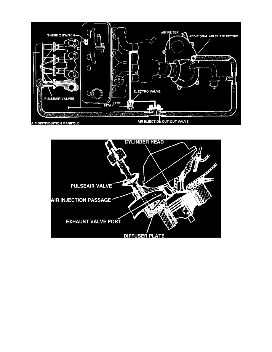
Fig. 6 Pulse air valve type air injection system
Fig. 7 Air injection ports
This system, Fig. 6, is used to reduce hydrocarbon (HC) and carbon monoxide (CO) emissions by injecting air into the exhaust manifold. The system
consists of an air filter with an additional fitting, air injection cut-out valve, electro valve, air distribution manifold, 4 pulse air valves, diffuser plate on
which the pulse air valves are mounted and a specially designed cylinder head incorporating passages into the exhaust valve ports to permit air injection,
Fig. 7. The air injection system uses the existing vacuum in the cylinder head exhaust ports. A predetermined amount of filtered air is drawn in through
the air distribution manifold and to the pulse air valves. The pulse air valves then introduce air injection to each exhaust port. The exhaust ports in the
cylinder head are subjected to variations in pressure and vacuum due to the evacuation of the exhaust gasses and cycling operation of the engine. When
the exhaust valves are open, there is no air injection. When the exhaust valves are closed, exhaust gasses remaining in the exhaust manifold and exhaust
pipes retain a certain discharge speed and momentum, creating a momentary vacuum within the exhaust ports. This vacuum brings about the necessary
air injection.
The Air Injection system injects air into the exhaust ports during initial start-up of the engine and while coolant temperature is below 104°F. When
coolant temperature increases above 104°F, the air injection cut-out valve closes, stopping air injection to the exhaust ports.