
505 V6-2849cc 2.8L ZN3J (1987)
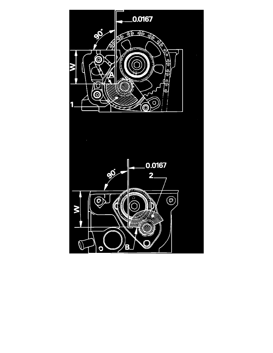
Fig. 35 Counterweight check for proper setting
7.
Check counterweights for proper setting, Fig. 35, as follows:
a. Place non-angled end of gauge 0.0167 on face (A) of front counterweight (1).
b. Place angled end of gauge 0.0167 under face (B) of rear counterweight (2).
c. Check distance W between counterweight faces (A) and (B) and valve cover gasket plane of the cylinder head. This distance must lie between
gauge marks; if not, carry out counterweight setting procedure. A counterweight set incorrectly by one tooth will cause a .2-.4 inch
variation in distance W depending upon point of measurement on counterweight.