
Acclaim L4-153 2.5L SOHC (1990)
Automatic Shut Down (ASD) Relay: Testing and Inspection
Main Relay testing and inspection can also be found at Powertrain Management / Computers and Control systems / Testing and Inspection / Procedures /
Diagnostic Charts / No Start (NS) Tests / NS-14 Repairing Fault "ASD Relay Circuit".
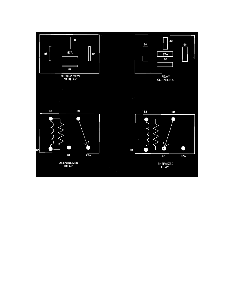
Relay Terminal Identification
AUTOMATIC SHUT DOWN (ASD) RELAY TERMINAL IDENTIFICATION
The following is a list of the terminal numbers, with circuit codes, and color codes, and their function:
Circuit No. Terminal No.
Color Code
Description
A14
30
RD/WT
Has battery input voltage supplied through fusible link.
A61
87
DG/BK
Connected to terminal 30 in the energized position, supplies output voltage to the fuel pump, fuel
injectors, ignition coil, and 02 sensor heater element.
A21
86
DB
Connected to the ignition circuit, provides supply voltage to the relay.
K51
85
DB/YL
Connected to the Single Board Engine Controller (SBEC), and grounded by the SBEC, to activate the
relay when the ignition switch is in the START or RUN position and a distributor signal is present.
N/A
87A
N/A
Not used in these applications.
AUTOMATIC SHUT DOWN (ASD) RELAY TEST
NOTE: The following test procedures assume that the ignition system is functioning, and that a good spark is evident at the plugs. If this not the case
test the ignition system before proceeding with this test.
NOTE: Automatic Shut Down (ASD) relay operation may be tested with the use of the DRB II scanner or equivalent.
If no scanner is available proceed with the following test.
1.
Using a digital voltmeter connect the negative lead to ground and the positive lead to the terminal 30 (RD/WT) wire of the ASD relay connector.