
Acclaim L4-153 2.5L SOHC Flex Fuel (1994)
Ignition Coil: Description and Operation
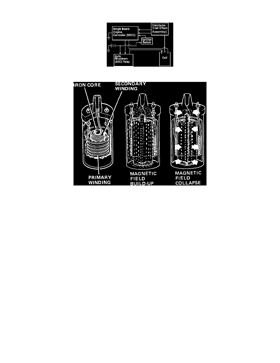
System Schematic Diagram
Ignition Coil Operation (Coil Construction May Vary)
PURPOSE
Coil produces a secondary voltage (25,000-35,000V), capable of arcing across the spark plug gap and igniting the air/fuel mixture, under all
operating conditions.
PURPOSE
Steps up primary voltage of 12 Volts to a secondary voltage great enough to arc across the spark plug gap, and ignite the air fuel mixture,
(25,000-35,000 Volts).
OPERATION
The PCM uses the Camshaft and Crankshaft Position (CKP) sensor inputs to determine when to charge and fire the coils.
The Powertrain Control Module (PCM), Controls Ignition Dwell And Timing Through The Coil Primary Ground.
Power is supplied to the positive side of coils by the ASD relay.
When the primary windings of a coil are grounded, current flow in the windings generates an electromagnetic field. (Low primary resistance of
0.57-0.7 ohms, allows the PCM to fully charge each coil in a very short period).
The electromagnetic field is concentrated by the iron core.
When the ground is removed, the concentrated field collapses, inducing high voltage in the secondary windings.
This high voltage is routed to the spark plugs via the distributor rotor, cap, and secondary ignition wires.
CONSTRUCTION
Secondary winding, (thousands of turns of light gauge wire) wound around a soft iron core.
Primary winding, approximately 200 turns of heavier (approximately No. 18 gauge) wire, wrapped around the secondary windings.