
Acclaim L4-153 2.5L SOHC Flex Fuel (1994)
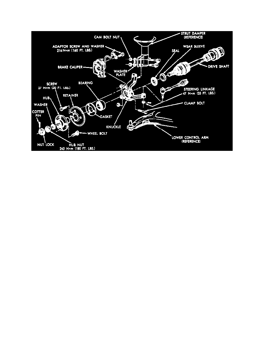
Rear Knuckle: Service and Repair
REMOVAL
1. Remove wheel hub cotter pin, locknut and spring washer.
2. Loosen hub nut with brakes applied. The hub and driveshaft are splined together through the knuckle and retained by hub nut.
3. Raise and support vehicle.
4. Remove front wheel and the hub nut. Ensure splined driveshaft is free to separate from spline in hub during knuckle removal. A pulling force on
the shaft can separate the inner Constant Velocity (CV) joint. Tap lightly with a brass drift, if required.
5. Disconnect tie rod end from steering arm with puller tool No. C-3894-A, or equivalent.
6. Disconnect brake hose retainer from strut damper.
7. Remove clamp bolt securing ball joint stud into steering knuckle and brake caliper adapter screw and washer assemblies.
8. Support caliper with a piece of wire. Do not allow to hang by brake hose.
9. Remove rotor.
10. Separate ball joint stud from knuckle assembly, then pull knuckle out and away from driveshaft. Do not permit driveshaft to hang after separating
steering knuckle from vehicle.
INSTALLATION
1. Place steering knuckle on lower ball joint stud and driveshaft through hub.
2. Install and tighten ball joint to steering knuckle clamp bolt to specifications.
3. Install tie rod end into steering arm and tighten nut to specifications. Install cotter pin.
4. Install rotor.
5. Install caliper over rotor and position adapter to steering knuckle. Install adapter to knuckle bolts and torque to 160 ft-lbs.
6. Attach brake hose retainer to strut damper and tighten screw to specifications.
7. Install washer and hub nut, then with brakes applied, tighten hub nut to specifications.
8. Install spring washer, locknut and new cotter pin.