
Acclaim L4-153 2.5L SOHC Turbo (1989)
Axle Shaft: Service and Repair
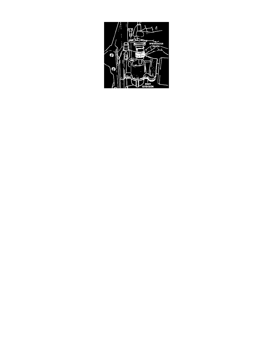
Fig. 3 Speedometer Pinion Replacement
REMOVAL
Inboard C/V joints have stub shafts splined into differential side gears, or splined into the intermediate shaft on right side of an equal length
system. Driveshafts are spring loaded and are retained to side gears by constant spring pressure provided by spring contained in C/V joints.
1. Remove cotter pin, lock and spring washer, then the hub nut washer and wheel assembly.
2. If removing the righthand driveshaft, speedometer pinion must be removed prior to driveshaft removal.
3. Remove clamp bolt securing ball joint clamp bolt to steering knuckle, then separate ball joint stud from steering knuckle. Do not damage ball
joint or C/V joint boots.
4. Separate outer C/V joint splined shaft from hub by holding C/V housing while moving knuckle/hub assembly away from C/V joint. Do not
damage slinger on outer C/V joint. Do not attempt to remove, repair or replace.
5. Support assembly at C/V joint housings and remove by pulling outward on the inner C/V joint housing. Do not pull on shaft. If removing
lefthand driveshaft assembly, removal may be aided by inserting a screwdriver blade between differential pinion shaft and carefully
prying against end face of stub.
6. Remove driveshaft assembly from vehicle.
INSTALLATION
1. Hold inner joint assembly at housing while aligning and guiding inner joint spline into transaxle. On equal length systems, ensure rubber
washer seal is in place on right inner C/V joint.
2. On all models, push knuckle/hub assembly out and install splined outer C/V joint shaft into hub.
3. Install knuckle assembly on ball joint stud.
4. Install clamp bolt. Torque to 70 ft. lbs.
5. Install speedometer pinion.
6. Fill differential to bottom of filler plug hole with Dexron automatic transaxle fluid.
7. Install washer and hub nut. Torque hub nut to 180 ft. lbs. Install nut lock and cotter pin.
8. If, after attaching driveshaft assembly in vehicle, the inboard boot appears collapsed or deformed, vent the inner boot by inserting a round tipped,
small diameter rod between boot and shaft. As venting occurs, the boot will return to normal shape. After installation of driveshaft, check
driveshaft length. See: Specifications