
Acclaim V6-181 3.0L SOHC (1990)
Suspension Control Module: Description and Operation
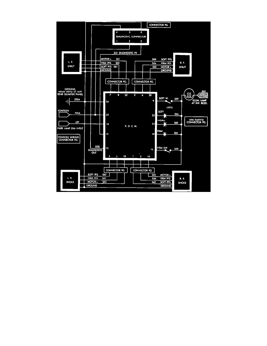
Fig. 2 Variable Dampening Suspension Wiring Circuit
The Variable Damping Control Module (VDCM), is used to monitor and control the Variable Damping Suspension (VDS) system. The VDCM has
one 25-Way connector and is attached to a bracket in the lefthand side of the trunk. The 6-way VDCM diagnostic connector, also located in the trunk,
can be used to access diagnostics with a DRBII or equivalent scan tool. The VDS system, including the VDCM, is grounded at the left rear quarter
panel inside the trunk (circuit Z02A).
VDCM INPUTS
The VDCM receives power from the battery through the ignition switch, (circuit F20A).
The VDCM receives information from two selector switches located on the center console. The position of these switches tell the module which
damping position has been selected.
The VDCM also monitors and receives information from eight Position Feedback Switches (PFS). Two PFS's are located in each shock/strut. PFS's
indicate the present damping position of the shocks/struts.
VDCM OUTPUTS
The VDCM controls four small electric motors, one in each shock/strut. These motors vary the sizes of the fluid orifices in the shock/struts to achieve
the different damping positions.
The VDCM also controls three LEDs on the switch bezel in the center console which indicate the present setting of the VDS system. The VDCM dims
the LEDs when the headlamps are On and brightens the LEDs when the headlamps are Off. The VDCM uses the park lamp dim input (pin 14) to
determine is the headlamps are On or Off. The LEDs are also used to inform if a system fault occurs.
VDCM RESET
The VDCM has a volatile memory and will reset whenever the ignition is turned ON. When the VDCM is reset it will: Clear the VDCM memory of
any faults; Read selector switch inputs; Attempt to drive the motors in the shocks/struts to the selected damping position if they are not already in the
selected position.