
Breeze L4-2.4L VIN X (2000)
1. Disconnect battery.
2. Disconnect the connector from its mating half/component.
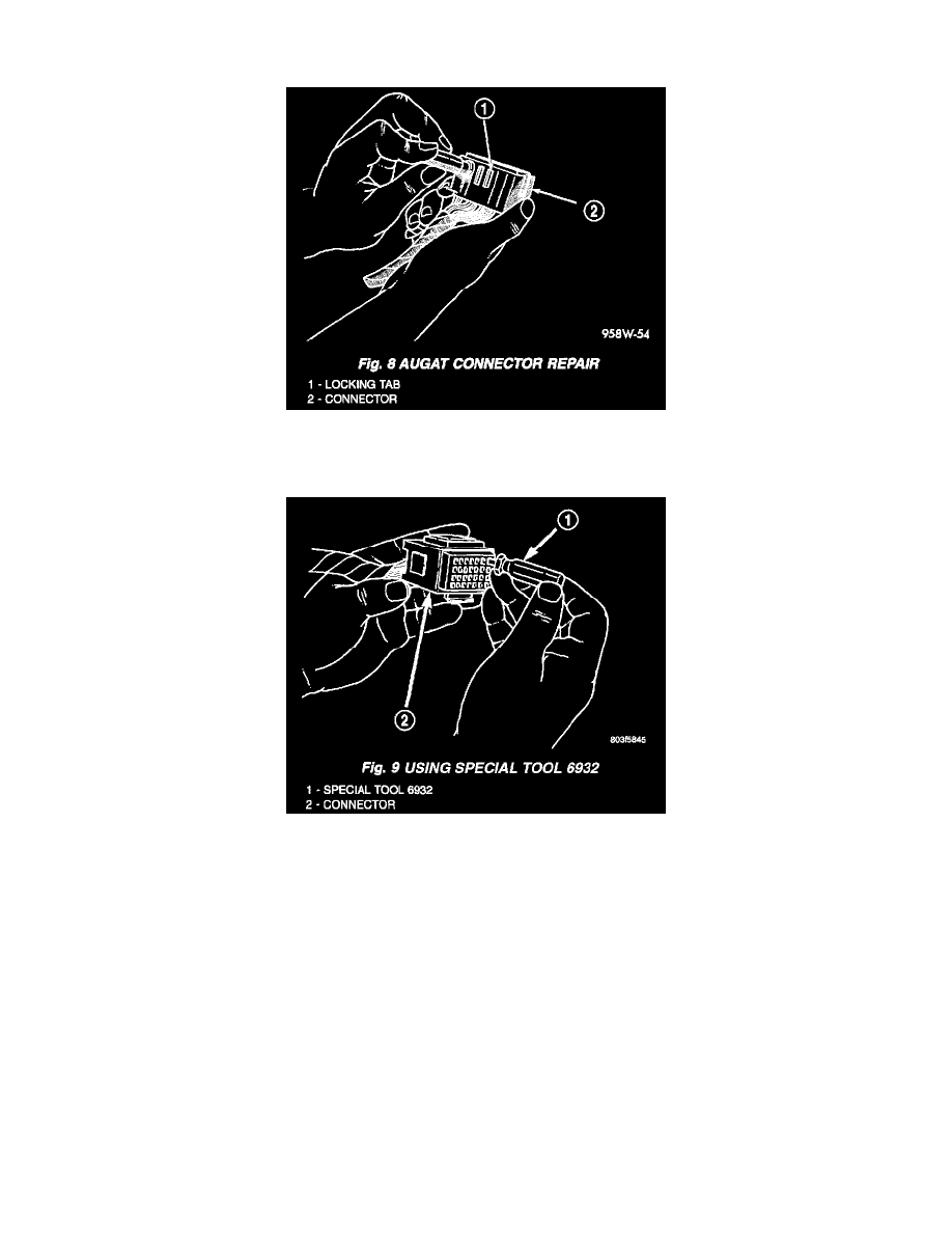
Fig.8 Augat Connector Repair
3. Push down on the yellow connector locking tab to release the terminals (Fig. 8).
Fig.9 Using Special Tool 6932
4. Using special tool 6932, push the terminal to remove it from the connector (Fig. 9).
5. Repair or replace the terminal as necessary.
INSTALLATION
1. Reset the terminal locking tang.
2. Insert the removed wire in the same cavity on the repair connector.
3. Repeat steps for each wire in the connector, being sure that all wires are inserted into the proper cavities. For additional connector pin-out
identification, refer to the wiring diagrams.
4. When the connector is re-assembled, the locking tab must be placed in the locked position to prevent terminal push out.
5. Connect connector to its mating half/component.
6. Connect battery and test all affected systems.
Wiring Repair
When replacing or repairing a wire, it is important that the correct gauge be used as shown. The wires must also be held securely in place to prevent
damage to the insulation.
1. Disconnect battery negative cable.
2. Remove 1 inch of insulation from each end of the wire.
3. Place a piece of heat shrink tubing over one side of the wire. Make sure the tubing will be long enough to cover and seal the entire repair area.